background image

R

3-13

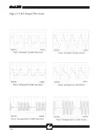
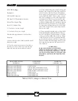
Figure 3.2 Waveform Generator Output

Summary of Contents for Sabre 2400

Page 1: ...Operator Service Manual R ...

Page 2: ...nded person is mandatory CONMED will provide assistance if needed in safeguard precautions necessary to avoid any question of warranty responsibility U S Patent Nos 4 569 345 4 617 927 4 848 335 4 961 739 and other patents pending 2004 CONMED Corporation Mailing Address 310 Broad Street Utica New York 13501 Shipping Address 7211 S Eagle St Englewood Colorado 80112 For Technical Services or Return ...

Page 3: ...4 1 Front Panel Controls and Displays 2 3 2 4 2 Output Panel 2 5 2 4 3 Rear Panel 2 6 2 5 Operating Instructions 2 8 2 5 1 Preliminary Setup 2 8 2 5 2 Operation 2 9 3 0 THEORY OF OPERATION 3 1 3 1 Circuit Theory of Operation 3 1 3 1 1 Functional Block Diagram Description 3 1 3 1 2 Power Supplies 3 1 3 1 3 Controller Hardware 3 2 3 1 3 1 Watchdog Timer 3 2 3 1 3 2 Power On Reset 3 3 3 1 3 3 Control...

Page 4: ...Return Monitor A R M Calibration Check 4 7 4 6 Calibration and Adjustments 4 8 4 6 1 CAL Mode General Information 4 8 4 6 2 Power Calibration General Information 4 10 4 6 3 Output Power Calibration Procedure 4 11 4 6 4 A R M Calibration Pad 4 12 4 7 Troubleshooting 4 13 4 7 1 HLP Codes 4 13 4 7 2 Pseudo Run Diagnostics dIA 2 4 13 4 7 3 Watchdog Timer Troubleshooting 4 16 4 7 3 1 Accessing Watchdog...

Page 5: ... 33 4 6 Power Board Assembly 4 34 Figure Title Page R 4 1 Functional Block Diagram 4 35 4 2 CPU PIA 4 36 4 3 Vbase Speaker Relay Voltage Regulators 4 37 4 4 ADC and Waveform Generator 4 38 4 5 Display Drivers 4 39 4 6 RF Amp Output Arm Isolation Power Supplies 4 40 4 7 Hand and Foot Switching 4 41 4 8 Seven Segment Displays Drivers 4 42 4 9 Indicators Drivers 4 43 Schematic Title Page 4 1 RF Outpu...

Page 6: ...R This page intentionally left blank ...

Page 7: ...tion with a fault tolerant design provides a wide safety margin against catastrophic failures Microprocessor Control this feature provides the user with a superior degree of safety and con trol in solid state electrosurgery The programmed intelligence of the microprocessor has been exploited to provide accurate therapeutic power digital power display microprocessor aided calibration and a comprehe...

Page 8: ...ollable by the design of this equipment It is important that the instructions supplied with this equipment be read understood and followed in order that safety and effectiveness be enhanced 1 1 1 Precautions in Equipment Preparation Visually inspect all accessories before each use to verify the integrity of insulation and the absence of obvious defects The Sabre 2400 is equipped to connect three m...

Page 9: ...d dry Avoid placement on scar tissue bony promi nences or other areas where pressure points on small areas might develop Because of the risk of burns needles should never be used as return electrodes for electrosur gery Return electrodes should be placed such that as much of their conductive area as possible is in firm contact with an area of the patients body that has a good blood supply and as c...

Page 10: ...to circumcision clamps Apparent low power output or failure of the electrosurgical equipment to function correctly at otherwise normal settings may indicate faulty application of the return electrode failure of an electrical lead or excessive accumulation of tissue on the active electrode Do not increase power output before checking for obvious defects or misapplication Check for effective contact...

Page 11: ...ts is intermittent in nature with duty cycles on the order of 10 this unit is not designed to operate for extended periods of continuous output When testing it is recommended that duty cycles be limited to 15 seconds on 30 seconds idle Life of the equipment will be extended by minimizing operating temperature and extreme thermal cycles The heat dissipation capability of the heat sink is severely i...

Page 12: ...di tionally are 150mA max with accessories per IEC 601 2 2 Clause 19 101 b when used with approved accessories See CONMED IEC Recognized Electrosurgical Accessories list Cat No 60 5206 001 Bipolar Less than 1 per IEC 601 2 2 Clause 19 101 c RF Floating Isolated POWER DECREASE 1 typical Pure Cut at 150W 20 seconds SINGLE FOIL RETURN ELECTRODE MONITOR Two wire continuity detector typical threshold 1...

Page 13: ...ORS Monopolar Cut Mode Indicator Yellow LED Monopolar Coag Mode Indicator Blue Incandescent Light Bipolar Mode Indicator Blue Incandescent Light Monopolar Cut Power Digital Display Red LED digital displays Monopolar Coag Power Digital Display Red LED digital displays Bipolar Power Digital Display Red LED digital displays Return Monitor Indicator Red LED Resistance Indicator Green LED bar graph Ret...

Page 14: ...ith air or with oxygen or nitrous oxide Continuous operation with intermittent loading Duty Cycle 15s on 30s off Operating Ambient temperature range 10O C to 40O C Relative Humidity 30 to 75 Altitude 60 to 4500 meters 197 to 14 760 feet above Sea Level Mounting Restriction 2 inch 5cm clearance required on each side of unit for cooling SHIPPING AND STORAGE ENVIRONMENTAL RESTRICTIONS 40O C to 70O C ...

Page 15: ...VICE F HIGH FREQUENCY PURE CUT WAVEFORM WITH MINIMUM THERMAL DAMAGE AND HEMOSTASIS BLEND CUT WAVEFORM WITH STANDARD MONOPOLAR COAGULATION HEMOSTASIS HANDSWITCHED OUTPUT CONNECTION FOR HANDSWITCHED MONOPOLAR FOOTSWITCHED OUTPUT CONNECTION FOR FOOTSWITCHED MONOPOLAR HIGH VOLTAGE OUTPUTS BIPOLAR OUTPUT CONNECTION FOR BIPOLAR ACCESSORIES ACCESSORIES ACCESSORIES REFER SERVICING TO QUALIFIED EXPLOSION R...

Page 16: ...R 1 10 Figure 1 2 Blend Cut Load Regulation Figure 1 3 Monopolar Coagulation Load Regulation ...

Page 17: ...d Regulation Figure 1 5 Output Power vs Power Setting 300 300 250 250 200 200 150 150 100 100 50 50 0 0 POWER SETTING OUTPUT POWER WATTS Figure illustrates the output power delivered to the rated load for all available output modes ...

Page 18: ...R 1 12 This page intentionally left blank ...

Page 19: ... inch clearance around the unit to permit free circulation of air at the sides of the unit 2 3 PRELIMINARY CHECKS 2 3 1 Preliminary Functional Testing The following checks are recommended upon initial installation of the equipment and prior to each use of the instrument to avoid unnecessary delays in surgery See Figure 2 1 for location of controls and connectors 1 Ensure that the Power Switch is O...

Page 20: ...identical to depressing the Bipolar foot switch 9 Connect a two wire single pad Return elec trode to a Return Electrode jack Confirm that no Resistance Indicator bars are lit and the Return Monitor Indicator remains lit Press the Single Pad key to select single pad mode and confirm the Return Monitor Indicator extinguishes 10a Depress the Cut treadle of the Monopolar foot switch The Cut Activation...

Page 21: ...nerator tester as described in Section 4 Note that the power display of the tester will be most accurate when a noninductive resistor of the rated genera tor output impedance for the selected mode is used If no tester is convenient the availability of thera peutic current may be ascertained subjectively by attempting to cut and coagulate on surrogate tissue such as a piece of meat or fresh fruit a...

Page 22: ...t been properly established see Monitor Set Key The Resistance Indicator will light 2 to 8 bars when the patient s return electrode resistance is within range 12 BIPOLAR POWER DIGITAL DISPLAY Indicates the bipolar power level set via the Bipolar Power Level Control It is calibrated in watts deliverable to rated load 13 BIPOLAR POWER DECREASE KEY Decreases the output power level of the Bipolar mode...

Page 23: ...n mode 28 MONOPOLAR CUT POWER INCREASE KEY Increases the output power level of the selected cut mode Pure Cut or Blend when depressed 2 4 2 Output Panel The output panel contains the power circuit breaker and the required patient connection jacks for electrosurgery Refer to the OUTPUT PANEL portion of Fig 2 1 1 CIRCUIT BREAKER Primary power switch for the unit turns unit on and off Also provides d...

Page 24: ...H CONNECTOR A 3 pin threaded connector designed to accept a single treadle bipolar foot switch 3 POWER CORD Supplies ac mains power to the unit It should only be connected to a source of power corresponding to that listed on the nameplate Supplied with a standard 3 prong parallel blade hospital grade plug U S A Domestic only 4 NAMEPLATE Specifies Aspen model name serial number nominal line voltage...

Page 25: ...ISTANCE O 4 REAR PANEL I MODE 4 3 5 1 6 PURE POWER 2 1 POWER 2 7 BLEND 3 8 4 9 27 CUT 28 25 COAG MONOPOLAR 26 24 5 3 1 2 BIPOLAR 10 11 SET HI DUAL PAD SINGLE 5 12 6 13 POWER 21 RETURN MONITOR 23 22 BIPOLAR COAG 20 16 17 8 15 7 14 STORE SEL 18 PRESETS 19 F POWER HAND CONTROL FOOT CONTROL PATIENT CONNECTIONS ELECTRICALLY ISOLATED ...

Page 26: ...ory connections Connect the desired foot switchable bipolar acces sory to the two blue bipolar banana jacks Refer to Figure 2 2 If a hand switchable bipolar acces sory is to be used connect the RF lines to the two blue jacks with the switch connected between the black jack and the bottom blue jack WARNING ALWAYS STOW UNUSED ACCESSORIES IN A SAFE INSULATED LOCATION SUCH AS A HOLSTER 4 Connect the f...

Page 27: ...orresponding to activation mode Noting this wattage may be useful in attempt ing to derive similar surgical effects from several machines of different manufacturers The surgi cal effects obtained are dependent on a number of factors including waveform electrode size electrode geometry power level and surgical tech nique The size and geometry of monopolar electrodes are significant in that a large ...

Page 28: ...R 2 10 Figure 2 2 Patient Accessory Connections MONOPOLAR BIPOLAR O I BIPOLAR F POWER HAND CONTROL FOOT CONTROL PATIENT CONNECTIONS ELECTRICALLY ISOLATED ...

Page 29: ...on the base and the two pole circuit breaker CB1 mounted on the output panel CB1 serves both as a lighted power switch and to protect the unit from over loads On overload this device automatically switches its handle to the OFF position The switched AC is wired to TB1 for connection to the primary windings of power transformer A5T1 Strapping options on TB1 set the unit for a given mains voltage ra...

Page 30: ...ilure This is accomplished by requiring the micropro cessor to write to the WDT once during each program execution cycle This WRITE PULSE is referred to as the Watchdog Timer Strobe WDSTR Each cycle is 25 2 milliseconds long The WDT circuit must hear from the microprocessor within a 18 to 34 msec window If the WDSTR occurs early because the pro gram skipped a portion of the software or late becaus...

Page 31: ... 3 1 3 2 Power On Reset The Power On Reset POR circuit consists of a single chip specifically designed for this function The POR circuit monitors 5 Vdc U50 8 and the output signals RST pin 5 and RS pin 6 become active if 5 Vdc falls below 4 75 Vdc The 8031 microprocessor operation is specified down to 4 5 Vdc This allows power supply mar gin for proper power down of the controller until reset occu...

Page 32: ...ding when PSEN is high to select one of the two PIA devices The nonvolatile EEPROM memory U4 is a serial device which stores calibration coefficients and program presets Validity of these values is insured by also storing a CRC check sum anytime these values are changed When the ESU is powered up the data stored in the non volatile section of U4 is automatically copied onto the static RAM where it...

Page 33: ...enting occur on the rising edge of the 20 MHz clock when SRLOAD U25 11 goes low and then high U25 also generates 2 5 MHz and 10 MHz clocks from the 20 MHz oscillator Y1 for clocking the Display Keyboard Driver Encoder U26 and the microprocessor U3 Each time SRLOAD goes low and then high the waveform address counter formed by U23 and U24 advances its count The outputs from this counter WVA0 6 selec...

Page 34: ...data memories are func tioning properly and without crosstalk 11 Verify that the contents of program memory in all locations where the program resides is intact using a 16 bit cyclic redundancy check 12 Verify that the contents of the calibration data is intact using a 16 bit cyclic redundancy check 13 Verify that the contents of the preset data is intact using a 16 bit cyclic redundancy check 14 ...

Page 35: ...y signal DISLE At power on reset all HV5708 drive chips are blanked during the reset period by a reset driver ULN2003 U13 F 3 1 5 1 Keyboard A membrane switch panel is integrally mounted in the display The switches form a 5x3 matrix which is scanned by PIA U10 and debounced in software 3 1 6 Power Amplifier The Power Amplifier PA is a hybrid cascode amplifier made up of four high voltage bipolar t...

Page 36: ...ith no output Bipolar Coag Mode uses a fixed VBASE and var ies the number of pulses per cycle period to con trol output power See Figure 3 2 for representa tive BGATE drive waveforms 3 1 7 RF Output Section CAUTION Because of the high peak to peak amplitudes of these waveforms use oscillo scope probes that can withstand 2 KVpp mini mum for cut 10 0 KVpp minimum for coag and 500 Vpp minimum for bip...

Page 37: ...A2 PWB via the VARM signal line This current feeds into the center tap of T4 primary The voltage on the center tap is the average of the two collector volt ages so it appears as a full wave rectified sine wave with a peak amplitude of one half that on either collector Inductor L1 helps hold the cur rent fed to T4 constant regardless of these voltage variations while C65 serves as a bypass to limit...

Page 38: ...ignificant electrode detachment A Return Fault declared in this case will NOT auto matically be cleared if the patient resistance drops back to near the stored value The Monitor Set Key must again be pressed to register the staff s satisfaction that the electrode attachment is safe before turning off the alarm Because patients and return site resistances vary over a considerable range it is not sa...

Page 39: ...all sections are identical The secondary winding T2 8 and T2 7 combine with D16 and C59 to produce an isolated dc voltage When the bipolar hand switch is closed the emitter of Q16 is pulled to the return of it s isolated power supply turning Q16 on With Q16 turned on current flows through the LED of the optocoupler U10 turning its output tran sistor on This results in BIP H going low and signallin...

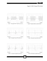
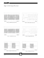
Page 40: ... is the BGATE signal A2TP23 is the GATE signal Note The lower trace in each oscillogram is A2TP14 and is used as the trigger point source Where there is noticeable aliasing in the bipolar modes an expanded view of the waveform is included for clarity ...

Page 41: ...R 3 13 Figure 3 2 Waveform Generator Output ...

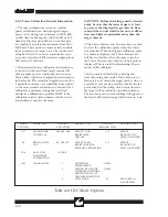
Page 42: ...R 3 14 Figure 3 3 RF Output Waveforms ...

Page 43: ...R 3 15 Figure 3 3 RF Output Waveforms ...

Page 44: ...R 3 16 Figure 3 3 RF Output Waveforms ...

Page 45: ... forward and lift its front edge The Top Cover can be held open vertically by sliding the Rear Support Bracket Slots onto the top edge of the Base Assembly See Figure 4 2 To close the Top Cover lift it upward until the Support Bracket Slots are free and then lower it onto the Base Assembly Reengage the Front Closure Pins into the Base Assembly slots before replacing the rear screws 4 2 1 Power PWB...

Page 46: ...el punctures or dents 4 5 PERIODIC PERFORMANCE TESTING The Sabre 2400 should be performance tested at least every six months Every unit is supplied with a serialized Production Test Data Sheet that tabulates the results of the factory tests that were performed on the unit This data is supplied so that it may be used as a reference for subsequent tests Recommended periodic performance tests are lis...

Page 47: ...ter in series with the 50W resistor and the unit s blue Bipolar Accessory Jacks 5 Perform the bipolar power tests indicated in Table 4 1 depending on the value of the load resistor used Note The RF output power level checks of Table 4 1 correct for the load regulation characteristics of the Sabre 2400 This results in output cur rent levels that may be different from the power setting when the P I2...

Page 48: ...ed maximum Hand control coag activations are accomplished by connecting a jumper between the lower black jack and the red jack of the desired hand switch able accessory jack 4 This measurement applies only to Sabre 2400 P N s 60 5600 003 and 60 5600 015 Measure A1 C67 and C68 in circuit resistance to confirm a value greater than 20M ohm resistance Temp orarily disconnect A1 J11 and measure RF leak...

Page 49: ...itchable accessory jack WARNING HAND CONTROL ACTIVATIONS SHOULD BE KEYED USING 3 OR LESS WELL INSULATED JUMPER S USE OF AN INSULATING ROD TO INSERT THE JUMPER IS ADVISED TO PREVENT RF BURNS CAUTION To avoid destroying the meter never activate output terminal connected to the meter 2 Disconnect the meter and resistor from the unit Turn unit Power Switch OFF MEASURED OUTPUT ACTIVATION MAXIMUM TERMIN...

Page 50: ...ent RF current from affecting leak age readings set all controls to zero 3 With all power controls set to 0 measure the leakage current as in step 1 from each of the three active output terminals to neutral See Table 4 5 while that output is activated in Cut by the appropriate foot switch or hand control jumper Hand control cut activations are accomplished by connecting a jumper between the lower ...

Page 51: ...Procedure 1 Disconnect all accessories from the Sabre 2400 front panel 2 Power up the Sabre 2400 in the RUN Mode Select Dual Foil Mode and confirm that Resistance Indicator has all 10 green bars flash ing the Monitor Set Key is flashing and that the Return Fault Indicator is illuminated 3 Using the test cable connect the DRB to the Return Electrode Jack 4 Adjust the DRB until eight bars of the Res...

Page 52: ...ed EEPROM CRC to match the computed value will result in declaration of a HLP 3 Fault code and shutdown of all output A special operational mode called CAL Mode permits the EEPROM data to be updated to compensate for circuit performance changes due to aging or replacement of components In CAL Mode the microprocessor guides the technician to simplify and expedite a complete and accurate calibration...

Page 53: ...ted sat isfactorily pressing the SEL Key will save all calibration changes and will return to the menu If the menu mode display for one of the three Calibration modes is flashing then one or more points in that mode is uncalibrated or nonmono tonic Pressing the SEL Key again will restore the menu from which the mode may be reen tered and calibration completed or corrected to fix the problem When t...

Page 54: ...nt Bear in mind that a unit which is far out of calibra tion may deliver considerably more than the target current The Power Increase and Decrease keys are used to select the calibration points when the unit is not activated When the highest calibration point in a mode is displayed the Power Increase key will have no further effect the same is true for the Power Decrease key when the lowest point ...

Page 55: ...he Bipolar Power Increase Key to set P in the Bipolar Power Window 6 Press SEL to move into the actual calibration The Power Windows will display the target value in amps or watts as determined above 7 Activate the unit and use the Power Increase Decrease Keys next to the mode being activated to set output to match the displayed target as closely as possible Deactivate when the best match occurs N...

Page 56: ...e speci fied on the nameplate 3 Press A2SW1 marked CAL on the micro control PWB while turning on the unit s circuit breaker Successful entry to CAL mode is signi fied by all segments of the display lighting 4 Press SEL The unit will then momentarily display CAL and proceed to display C C in the Cut Power Window Press the Cut Power Increase Decrease Keys to display Pad in the window 5 Press SEL to ...

Page 57: ...the HLP codes and other troubleshooting aids Upon fault detection the program will branch to an endless loop which displays a fault HLP code in the Monopolar Cut and Coag power level displays This loop takes RFEN false forces VBASE and the waveform generator output to zero drive condition and commands the relays to open Further it ceases generation of Watchdog Timer strobes and redundantly disable...

Page 58: ...n WDT timing parts incorrect pulse width is incorrect Microprocessor frequency incorrect Faulty A2U1 4538 Faulty A2U3 8031 Faulty A2U6 8255 Faulty A2U2 7400 5 RF PA supply Initialization Incorrect base voltage and operation Incorrect gate drive Shorted PA power transistor Shorted PA power FET A1 RVI shorted A5BR1 disconnected Shorted capacitor on RFSUP line ISENSE circuit faulty VSENSE circuit fau...

Page 59: ... 13 Detection of shorted Initialization Key press at power up key Shorted Keyboard Faulty A2U10 8155 17 Low AC line Fail Initialization Faulty A2U16 0838 and operation Faulty voltage sense CH2 0838 Inadequate AC mains 18 High AC line Fail Initialization Faulty A2U16 0838 and operation Faulty voltage sense CH2 0838 Excessive AC mains 19 External RAM Fail Initialization Faulty A2U3 8031 Faulty A2U10...

Page 60: ...hat signal and setting up an external generator and connecting it to the circuit is time consuming 4 7 3 1 Accessing Watchdog Timer Diagnostics dIA 1 To enter diagnostics 1 enter the CAL MODE per section 4 6 1 then select dIA in the Cut window by pressing the Cut Power I in Decrease Key The menu will display dIA 1 Press the SEL key again Since this mode is useful only with the RLYEN flag in the re...

Page 61: ...AC goes from approximately 5 0 Vdc at 0W to 2 8 Vdc at 300W The VDAC voltage at 300W will vary from unit to unit the important factor is that the voltage changes in small increments Next monitor A2TP6 and repeat the above proce dure Confirm that TP6 voltage increases from no more than 0 4V at 0W to approximately 5 0Vdc at 300W If it fails to do so check that VSENSE and ISENSE are both less than 0 ...

Page 62: ...peration with the ESU activat ed interference from electrosurgical current is the likely cause Check the A1T5 shield lid for good electrical and mechanical contact with the shield cup and capacitors A1C55 and C56 for proper value and connection Also check bypass capacitors A1C65 A2C27 and low pass filter capacitor A2C23 If the Resistance Indicator vs resistance test fails check 2VARM at A2TP13 wit...

Page 63: ...ansistors A1Q1 Q4 may be replaced singly without replacing the entire set Calibration should be checked after transistor replacement When replacing the power transis tors 1 Remove the entire Power Board Heatsink Assembly for easy access to the bottom of the PWB See Section 4 2 1 for detailed instructions 2 Remove the screw and compression washer from the transistor being removed Slightly bend the ...

Page 64: ...Serial Number Number Reference Designator and Description of Part CONMED Part Number if known Quantity Desired Mailing or Shipping Address Preferred Shipping Means if any Purchase Order Number if applicable Your Name If you are returning a unit obtain a Return Authorization Number from CONMED Tech Services This number should be marked on the outside of the carton Variable output at TP 5 Descriptio...

Page 65: ...03 CAP 1 5 nF 2000V 10 PP C27 C28 62 1675 001 CAP 5 6 nF 2500V 5 PP C35 42 47 59 66 62 0268 001 CAP 10uF 16V 20 ELECT C43 45 48 50 55 56 60 62 1677 004 CAP 0 33 uF 100V 10 MET POLY C52 62 0267 004 CAP 100pF DIP CER C53 54 62 1677 005 CAP 0 22 uF 100V 10 MET POLY C62 62 1675 003 CAP 2 7 nF 2000V 5 PP C63 64 62 1676 002 CAP 10 nF 1600V 10 PP C67 62 1678 002 CAP 180pF 6KV 20 C68 62 1678 001 CAP 150pF...

Page 66: ... 2W 5 CF R69 62 0364 003 RES 3 3 1 4W 5 R70 BI05 0081 RES 1 5W 5 004 Assembly ONLY R70 62 1693 005 RES 0 47 3W 5 Power Oxide 005 ONLY RV1 62 4594 004 VARISTOR 17 VAC TP1 15 17 18 62 2725 001 TEST POINT T1 61 4764 003 TRANSFORMER BIPOLAR T1 61 4764 001 TRANSFORMER BIPOLAR T2 61 4870 002 TRANSFORMER CONT DETECT 001 ASSY T2 61 4870 001 TRANSFORMER CONT DETECT 002 ASSY T3 61 4887 001 TRANSFORMER MONOP...

Page 67: ...ANSISTOR VN0116N3 Q5 62 4239 001 TRANSISTOR 2N3904 Q6 62 1696 001 TRANSISTOR NPN HIREL LM395 R1 62 0961 314 RESISTOR 18 2K 1 4W 1 MF R2 62 0961 340 RESISTOR 34 0K 1 4W 1 MF R3 62 0961 185 RESISTOR 825 1 4W 1 MF R4 10 11 15 17 24 26 62 0961 222 RESISTOR 2 00K 1 4W 1 MF R5 62 0961 464 RESISTOR 665K 1 4W 1 MF R6 34 62 0961 391 RESISTOR 115K 1 4W 1 MF R7 66 62 0364 039 RESISTOR 100 1 4W 5 CC R12 35 52...

Page 68: ...PE U12 62 3394 001 IC LM324 U13 14 62 1374 001 IC ULN2003 U15 62 1362 001 IC LM358 U16 62 4850 001 IC ADC0838ACN U17 62 1716 002 IC 74HCT74 U19 20 21 62 4851 002 IC HV5308 32 CHAN SRL PARL U22 62 4253 001 IC 74S140 U23 24 25 62 1711 001 IC 74LS163 U26 62 4254 001 IC 74LS166 U27 61 4792 001 IC Sabre 2400 WAVEFORM PROGRAM EPROM U30 62 1715 001 IC 74LS02 U50 62 4258 002 IC LTC1232 VR1 62 4603 003 VOL...

Page 69: ...1 CONTROL PANEL A7 61 4913 001 A7 DISPLAY ASSEMBLY N A 62 4781 001 CABLE FLAT RIBBON A2 N A 62 7032 001 BRACKET RIGHT N A 62 7032 002 BRACKET LEFT N A 62 4926 001 BUMPER RUBBER N A 62 4286 001 INSULATOR CLAMP TO220 N A 62 0649 002 LOCTITE 222 N A 62 1575 002 SCREW 6 32 X 25 SOCKET HD CAP N A 62 4772 001 SEAL GASKET N A 62 0343 002 6 KEP NUT N A 62 0342 004 6 NUT N A 62 1752 001 WIRE BRAID N A 62 1...

Page 70: ...CRIMP TERMINAL N A 62 0337 002 FOOT PLASTIC 5 8 BLACK N A 62 4786 001 HANDLE ROUND Sabre 2400 N A 62 0259 001 MOUNT CABLE TIE N A 62 0753 003 NUT HEX NYLON 63 32 N A 62 0343 001 NUT KEPS 4 40 N A 62 0343 004 NUT KEPS 20 32 N A 62 0343 002 NUT KEPS 6 32 N A 62 4814 001 SCREW 10 24 X 1 2 SELF TAPPING N A 62 0377 005 SCREW 6 32 X 3 8 BHS N A 62 0383 004 SCREW 6 32 X 5 16 FHS N A 62 4172 003 SCREW 6 3...

Page 71: ...0418 006 LOCK WASHER INT TOOTH 1 4 N A 62 5107 001 LOCK WASHER INT TOOTH 3 8 N A 62 0418 008 LOCK WASHER INT TOOTH 5 16 N A 62 0343 001 NUT KEPS 4 40 N A 62 4109 001 OVERLAY OUTPUT PANEL N A 62 3729 001 PANEL OUTPUT WITH SELECTOR WHEEL N A 62 4196 001 RETAINING RING EXTERNAL 3 16 N A 62 4197 001 RETAINING RING EXTERNAL 3 32 N A 62 4404 001 SCREW TYPE B SELF TAP 4 PAN HD N A 62 0370 001 SCREW 6x3 8...

Page 72: ...02 RES NET 5X200 6 PIN SIP U1 U12 62 1374 002 IC DRIVER ULN2004 N A 62 4912 001 PWB DISPLAY A7 Sabre 2400 LED N A 62 2772 001 CONN SOCKET STRIP 10 PIN ASSEMBLY Footswitch Harness A5W1 A1P8 62 1389 005 CONNECTOR PLUG 6 PIN A5J1 62 0279 001 CONNECTOR 4 PIN A5J2 62 0279 002 CONNECTOR 3 PIN E1 2 62 0314 002 GROUND LUG 4 N A 62 0260 001 CABLE TIE 3 5 N A 62 1388 001 TERMINAL CRIMP N A 62 0339 004 TUBIN...

Page 73: ...35 4 961 739 AND PAT PEND US PATENT NOS 4 569 345 4 617 927 FOOTSWITCH FOOTSWITCH BIPOLAR MONOPOLAR COVER SCREWS REMOVE TO OPEN COVER ASSEMBLY IDENTIFICATION LABEL BASE ASSEMBLY Figure 4 1 Rear Panel Screw Locations ...

Page 74: ...A7 DISPLAY BOARD A2 CONTROLLER ASSEMBLY A1 POWER BOARD ASSEMBLY A6 OUTPUT PANEL ASSEMBLY A5 BASE ASSEMBLY A4 COVER ASSEMBLY A5T1 TRANSFORMER ASSEMBLY A3 CONTROL PANEL ASSEMBLY Figure 4 2 Subassembly Locations ...

Page 75: ...9 R38 R37 R42 R41 R40 D14 R59 R60 C49 C10 C32 C33 C34 C31 C24 C65 Q2 C E B R17 R10 B E C Q1 R54 C E B Q16 R44 R45 R43 Q12 B E C R48 R47 R46 C E B Q13 D15 R61 R62 R63 R55 R18 C46 R11 R13 R64 U1 R2 J3 C43 C45 C48 C50 R53 C47 R15 C4 C1 TP6 1 4 3 6 C15 C E B Q15 C54 C53 R51 Q14 B E C T5 U2 R23 R24 S D G Q6 T2 1 T2 2 C23 C9 T1 2 TP10 C8 C7 C A U10 K E TP5 D13 T2 10 C61 C52 C30 D12 T3 4 T3 1 J8 1 3 2 4 ...

Page 76: ... U7 U2 U4 U50 U1 U3 U6 U26 U23 U24 C49 C50 C51 C54 C55 C56 U13 R28 U14 R39 R18 R11 D9 C65 R10 U12 D8 R32 R30 R31 R13 R6 C18 C1 C48 C46 U22 U30 U29 C45 C53 C52 1 RN3 C E B Q3 C E B Q5 C2 R15 C75 1 RN4 R26 R27 R25 R22 R20 R23 C27 R24 U16 C23 U15 U10 U9 C63 61 4796 A2 MICRO CONTRL ASSY A K C72 C71 TP11 C39 U21 U20 VR2 1 2 3 C70 Y1 14 8 7 1 TP22 TP3 TP8 TP19 SW1 R36 C85 D14 C25 C9 C12 5VREF VBASE VSEN...

Page 77: ... 1 I7 I8 1 I10 1 1 I2 1 I5 1 I3 I1 1 61 4913 001 REV__ SABRE A7 DISPLAY ASSY I4 I9 I18 1 I19 U5 U9 RN1 U1 U2 RN2 U3 RN3 U4 RN4 RN9 RN5 RN6 RN10 U11 U6 RN11 U12 U8 U7 R6 R5 47 31 21 50 30 20 4 1 P1 47 31 21 50 30 20 4 1 P2 I14 1 RN8 RN7 Figure 4 5 Display Board Assembly ...

Page 78: ...WERAMP ASSEMBLY B E C Q3 Q5 G D S B E C Q4 R12 C2 T2 3 T2 4 D5 R20 Q11 B E C Q10 B E C R39 R38 R37 R42 R41 R40 D14 R59 R60 C10 C32 C33 C34 C31 C24 C65 Q2 C E B R17 R10 B E C Q1 R63 R18 R11 R13 R64 U1 J3 C43 C45 R15 C4 C1 TP6 1 4 3 6 C15 C E B Q15 C54 C53 R51 Q14 B E C T5 U2 R23 R24 S D G Q6 T2 1 T2 2 C23 C9 TP10 C8 C7 TP5 1 D13 T2 10 C52 C30 J8 1 3 2 4 5 6 BGATE COLL GATE 12 GND DRAIN GND RFSUP VB...

Reviews: