R
4-3
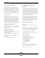
4.5.3 Output Power
Equipment:
Monopolar Foot switch
Bipolar Foot switch
0-1.5A RF Ammeter as a minimum. The most
accurate RF current measurements will result
when read on the upper 50% of the meter scale.
A set of meters including 150mA, 250mA,
500mA, 1.0A and 2.0A are recommended.
300, 400, or 500 ohm 250W noninductive resis-
tor
50, 100, or 125 ohm 50W noninductive resistor
Return Electrode Adapter Plug (shorting)
Bovie #12 Adapter Plug
3 test leads, 1m max. length
Procedure:
1. Use test leads to connect an RF ammeter in
series with the 250W resistor and one of the
unit's return electrode jack and the foot switch
controlled active jack.
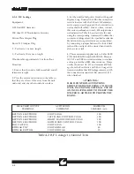
2. Perform the monopolar power tests indicated
in Table 4.1 depending on the value of the load
resistor used.
3. Disconnect the RF ammeter and load resistor
from the unit.
4. Use test leads to connect the RF ammeter in
series with the 50W resistor and the unit's blue
Bipolar Accessory Jacks.
5. Perform the bipolar power tests indicated in
Table 4.1 depending on the value of the load
resistor used.
Note: The RF output power level checks of Table
4.1 correct for the load regulation characteristics
of the Sabre 2400. This results in output cur-
rent levels that may be different from the power
setting when the P=I2*R calculation is done
at other than the rated load. Refer to the Load
Regulation Curves in Section 1 for details.
Mode
Power
Output
Power
Output
Setting
Current (mA)
Setting
Current (mA)
Monopolar
Pure Cut
300 ohms
300
949-1040
150
671-741
400 ohms
300
822-908
150
619-684
500 ohms
300
730-806
150
564-623
Blend Cut
300 ohms
180
739-812
90
520-574
400 ohms
180
634-700
90
489-539
500 ohms
180
562-620
90
449-496
Coag
300 ohms
120
596-659
60
417-461
400 ohms
120
520-574
60
368-406
500 ohms
120
465-513
60
329-363
Bipolar
50 ohms
50
949-1040
25
671-741
100 ohms
50
592-653
25
425-469
125 ohms
50
514-567
25
360-397
Table 4.1 RF Output Power Checks
Summary of Contents for Sabre 2400
Page 1: ...Operator Service Manual R ...
Page 6: ...R This page intentionally left blank ...
Page 16: ...R 1 10 Figure 1 2 Blend Cut Load Regulation Figure 1 3 Monopolar Coagulation Load Regulation ...
Page 18: ...R 1 12 This page intentionally left blank ...
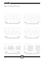
Page 41: ...R 3 13 Figure 3 2 Waveform Generator Output ...
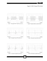
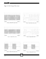
Page 42: ...R 3 14 Figure 3 3 RF Output Waveforms ...
Page 43: ...R 3 15 Figure 3 3 RF Output Waveforms ...


