background image


Cogswell Carrier for NVIDIA® Jetson™ TX2/TX2i  

Users Guide 

www.connecttech.com


Document: CTIM-00484 

Revision: 0.08 


Page 8 of 29 

Date: 2021-10-06 


Part Numbers / Ordering Information  

Part Number


ASG007 

Cogswell Carrier for NVIDIA® Jetson™ TX2/TX2i 


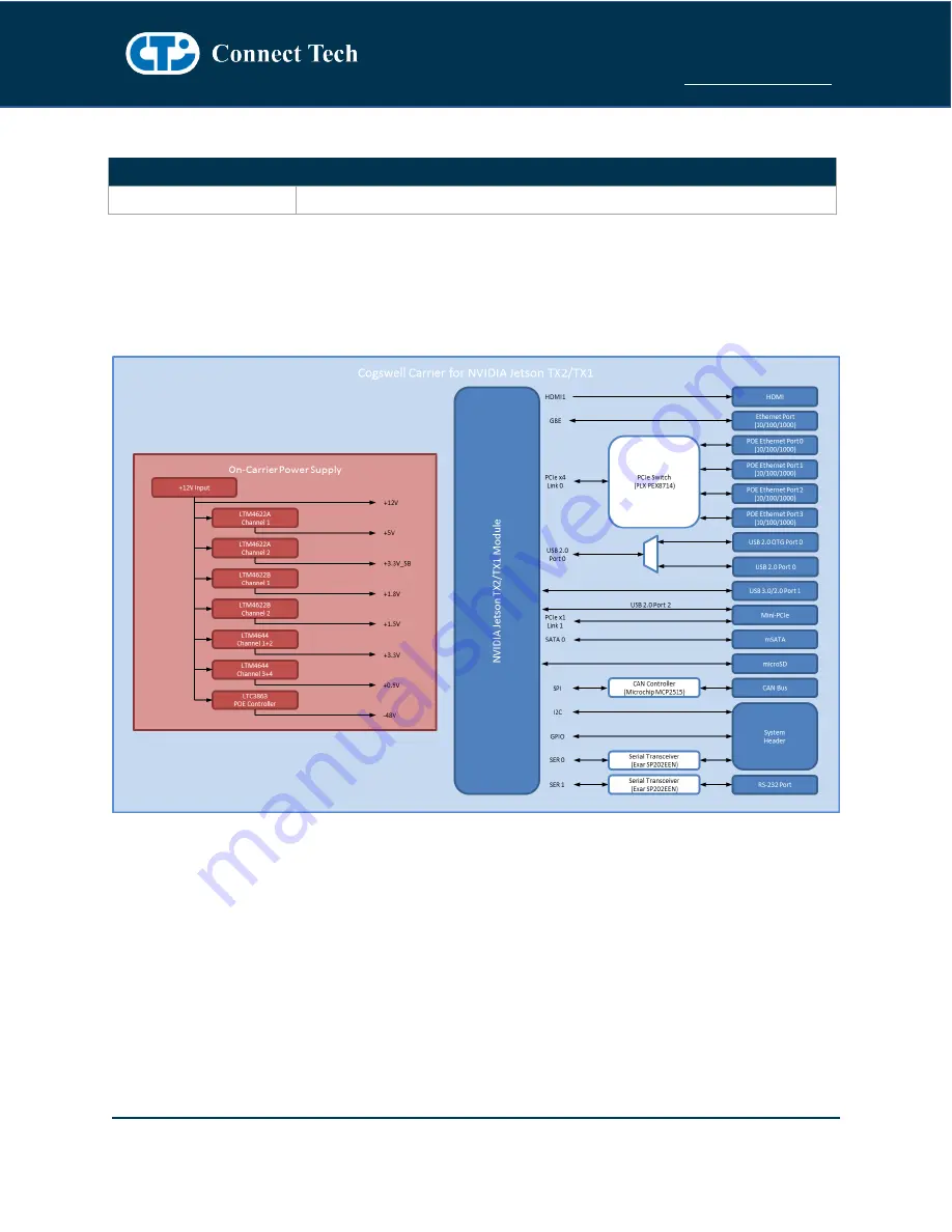
PRODUCT OVERVIEW 

Block Diagram 


Summary of Contents for ASG007

Page 1: ...Cogswell Carrier for NVIDIA Jetson TX2 TX2i CTIM 00484 Revision 0 08 2021 10 06 ...

Page 2: ... Locations Top Side 9 Connector Locations Bottom Side 10 Connector Summary 10 DIP Switch Summary Locations 11 DIP Switch Summary Locations 11 Jumper Summary Locations 11 Detailed Feature Description 12 Jetson TX2 TX2i Board to Board Connector 12 External Battery Header 13 HDMI Connector 13 Gigabit Ethernet 14 POE Gigabit Ethernet 14 GPIO Serial I2C 15 Serial 15 Mini PCIe mSATA Slots 16 Half and Fu...

Page 3: ... Recover 23 S3 Push Button Switch Reset 23 S4 Push Button Switch Power Button 23 J2 Jumper RTC Battery 24 J5 Jumper CAN Bus 24 Typical Installation 24 On Board Indicator LEDs 25 Current Consumption Details 25 Software BSP Details 26 Connect Tech s Custom L4T BSP CTI L4T 26 NVIDIA Jetpack for L4T 26 Force USB Recovery Mode 26 Thermals Details 27 Mechanical Drawings Models 28 Top View 28 Cables 29 C...

Page 4: ...t the reseller is unable to resolve your problem our highly qualified support staff can assist you Our support section is available 24 hours a day 7 days a week on our website at https connecttech com support resource center See the contact information section below for more information on how to contact us directly Our technical support is always free Contact Information Contact Information Mail ...

Page 5: ...the product prove to be irreparable Connect Tech Inc reserves the right to substitute an equivalent product if available or to retract the Warranty if no replacement is available The above warranty is the only warranty authorized by Connect Tech Inc Under no circumstances will Connect Tech Inc be liable in any way for any damages including any lost profits lost savings or other incidental or conse...

Page 6: ... metal object to dissipate any static charge that may be present on you Only handling circuit boards in ESD safe areas which may include ESD floor and table mats wrist strap stations and ESD safe lab coats Avoiding handling circuit boards in carpeted areas Try to handle the board by the edges avoiding contact with components REVISION HISTORY Revision Date Changes 0 00 2017 03 10 Initial Release 0 ...

Page 7: ...232 Serial Ports Product Features and Specifications Specifications Module Compatibility NVIDIA Jetson TX2 NVIDIA Jetson TX2i PCB Size Overall Size 178mm x 147 5mm 7 0078 x 5 8071 3D STEP Model download here Display 1x HDMI Supports up to HDMI 2 0 UHD 4K 2160p at 60Hz Ethernet 1x Gigabit Ethernet 10 100 1000 4 x POE Gigabit Ethernet 10 100 1000 4x IEEE 802 3af POE 15 4W or 2x IEEE 802 3aft POE 25 ...

Page 8: ...on TX2 TX2i Users Guide www connecttech com Document CTIM 00484 Revision 0 08 Page 8 of 29 Date 2021 10 06 Part Numbers Ordering Information Part Number ASG007 Cogswell Carrier for NVIDIA Jetson TX2 TX2i PRODUCT OVERVIEW Block Diagram ...

Page 9: ...Cogswell Carrier for NVIDIA Jetson TX2 TX2i Users Guide www connecttech com Document CTIM 00484 Revision 0 08 Page 9 of 29 Date 2021 10 06 Connector Locations Top Side ...

Page 10: ...or P2 External Battery External Battery Header P3 HDMI Port HDMI Right Angle Vertical Connector P4 NVIDIA Jetson TX2 TX2i Gigabit Ethernet RJ45 Gigabit Ethernet Connector 10 100 1000 P5 POE Gigabit Ethernet Ports 0 1 RJ45 Gigabit Ethernet Connectors 10 100 1000 P6 POE Gigabit Ethernet Ports 2 3 RJ45 Gigabit Ethernet Connectors 10 100 1000 P7 GPIO Serial Port GPIO RS 232 Samtec 2x6 Right Angle Head...

Page 11: ...witch Summary Locations Designator Function Description S2 Force Recovery Button Cogswell System Force Recovery Button Used for NVIDIA Jetson TX2 TX2i System Reprogramming with USB OTG Port S3 Reset Button Cogswell System Reset Push Button S4 Power Button Cogswell System Power ON OFF Button DIP Switch Summary Locations Designator Function Description SW1A Power Override Cogswell System Power Overr...

Page 12: ...ts to the Cogswell Carrier via a Samtec SEARAY Board to Board Connector Function NVIDIA Jetson TX2 TX2i Interface Location P1 Type Samtec SEARAY Connector Carrier Connector P N SEAM 50 03 0 S 08 2 A K TR 8 0mm stacking height Manufacturer Samtec Mating Connector P N SEAF 50 05 S 08 02 A K installed on Jetson TX2 TX2i Manufacturer Samtec Pinout Refer to NVIDIA s Jetson TX2 TX2i System on Module dat...

Page 13: ...x3 P N 53047 0310 Mating 51021 0300 Pinout Pin Description 1 RTC BAT 2 3 GND HDMI Connector Function HDMI Connector Location P3 Type TE Connectivity HDMI Right Angle Vertical Connector P N A35071TR ND Mating HDMI Type A Plug Cable CBG145 Pinout Pin Description Pin Description 1 TMDS2 2 GND 3 TMDS2 4 TMDS1 5 GND 6 TMDS1 7 TMDS0 8 GND 9 TMDS0 10 TMDS_CLK 11 GND 12 TMDS_CLK 13 CEC 14 15 DDC_CLK 16 DD...

Page 14: ...7 GBE_GND 8 MDI3_P 9 MDI3_N 10 MDI0_N 11 MDI0_P 12 GBE_GND 13 GND 14 ACT 15 GND 16 LINK POE Gigabit Ethernet Function POE Gigabit Ethernet Location P5 P6 Type Amphenol Dual RJ 45 Connector P N RJHSE 5381 02 Mating Any RJ 45 Plug with Cat5 5e 6 Cabling Pinout Pin Description Pin Description 1A GBEA_MDI0_P 2A GBEA_MDI0_N 3A GBEA_MDI1_P 4A GBEA_MDI2_P 5A GBEA_MDI2_N 6A GBEA_MDI1_N 7A GBEA_MDI3_P 8A G...

Page 15: ...he Intel 82574 For further details please see the CTIU 00010 Product Change Notification GPIO Serial I2C Function GPIO Serial I2C Location P7 Type Samtec High Temp Shrouded Terminal Strip P N HTSS 106 04 G D RA Mating Any 0 1 Pitch Connector Cable CBG258 Pinout Pin Description Pin Description 1 GPIO1 2 GPIO3 3 GPIO0 4 GPIO2 5 GND 6 7 GND 8 9 I2C_SDA 10 RS 232_0_RX 11 I2C_SCL 12 RS 232_0_TX The RS2...

Page 16: ...i PCIe module or a mSATA SSD module respectively The Mini PCIe slot contains a USB 2 0 link as per the Mini PCIe specification Half and Full Length Mini PCIe mSATA Module Installation The Cogswell Carrier is designed with mounting holes to allow for the population of full length modules To install a half length module you must use a Mini PCIe Half to Full Size Extension Bracket Function Mini PCIe ...

Page 17: ...DATA 11 PCIe CLK 12 UIM_CLK 13 PCIe CLK 14 UIM_RESET 15 GND GND 16 UIM_VPP 17 18 GND GND 19 20 W_DISABLE 21 RESV RESV 22 23 PCIe RX SATA TX 24 3 3V 3 3V 25 PCIe RX SATA TX 26 GND GND 27 GND GND 28 1 5V 1 5V 29 GND GND 30 SMB_CLK 31 PCIe TX SATA RX 32 SMB_DATA 33 PCIe TX SATA RX 34 GND GND 35 GND GND 36 USB D 37 GND GND 38 USB D 39 3 3V 3 3V 40 GND GND 41 3 3V 3 3V 42 ...

Page 18: ...SIM Card Slot Location P11 Type Molex SIM Card Connector P N 0475530001 Pinout Pin Description Pin Description 1 SIM_PWR 2 GND 3 SIM_RST 4 SIM_VPP 5 SIM_CLK 6 SIM_DATA 7 8 microSD Card Slot Function microSD Card Slot Location P12 Type Molex microSD Memory Card Connector P N 502570 0893 Pinout Pin Description Pin Description 1 SDIO_DATA2 2 SDIO_DATA3 3 SDIO_CMD 4 SDIO_VCC 5 SDIO_CLK 6 GND 7 SDIO_DA...

Page 19: ...o USB 2 0 Plug Pinout Pin Description 1 VBUS 2 DATA 3 DATA 4 ID 5 GND 6 Shield USB 2 0 OTG Client Mode and USB MUX To put the Cogswell into Client Mode the ID Pin on the Micro AB Connector needs to be pulled high Most USB Micro B Cables will do this internally Once in Client Mode the Cogswell will connect the OTG USB 2 0 Link to the Micro AB Connector and disable the USB 2 0 Type A connector using...

Page 20: ... installed to correctly configure the on board MUX which will link the Module to the Cogswell USB 3 0 re driver and connector Over current protection power supply filtering and ESD protection is provided on board NOTE Please note that USB3 0 support is NOT natively supported by the stock L4T builds For USB3 0 support users must deploy CTI L4T BSP Function USB 3 0 2 0 Location P15 Type Molex Type A...

Page 21: ...Auto Start Functionality which can be disabled The NVIDIA Jetson Modules require a power button or power pulse to start The Cogswell Carrier has a power pulse circuit on board to auto start the Module if the DIP Switch SW1B is correctly set Otherwise the NVIDIA Jetson TX2 TX2i Module will remain in an OFF state until the Power Button is pressed Note Due to the changes done to the PMIC circuitry of...

Page 22: ...ON The Cogswell Carrier has two DIP Switch block for various on board controls SW1 DIP Switch Carrier Power Control Function NVIDIA Jetson TX2 TX2i Power Control Location SW1 Pinout Switch Function Description ON OFF SW1A CARRIER_PWR_ON Override Internal Use Default SW1B PWR_BTN Auto Start Enabled Disabled See Auto Start Section regarding TX2i SW2 DIP Switch NVIDIA Jetson TX2 TX2i Selection and OT...

Page 23: ...he Connect Tech Board Support Package S2 Push Button Switch Force Recover Function NVIDIA Jetson TX2 TX2i Force Recover Location S2 Pinout Switch Description S2 FORCE_RECOV Switch Please see Force USB Recovery Mode for more details S3 Push Button Switch Reset Function NVIDIA Jetson TX2 TX2i Reset Location S3 Pinout Switch Description S3 RST_IN Switch S4 Push Button Switch Power Button Function NVI...

Page 24: ...tion Description ON 120 Ohm CAN P N Termination OFF No Termination TYPICAL INSTALLATION 1 Ensure all external system power supplies are off 2 Install the Jetson Module onto the Samtec SEARAY Connector P1 Be sure to follow the manufacturer s directions for proper installation of mounting hardware heatsink heatspreader and any other applicable requirements from the manufacturer 3 Install the heatsin...

Page 25: ...te maximum total draw of all functionality on the Cogswell Carrier Board not including Jetson Module 100 Below are measurements taken with the Cogswell Carrier running in various configurations Some values will change depending on what operation or software is installed Measurements also include the Jetson TX2 TX2i Module No mSATA or Mini PCIe modules were installed while taking these measurements...

Page 26: ...T The Jetpack for L4T is an on demand all in one package that bundles and installs all software tools required to develop for the NVIDIA s TX2 TX2i Platform with Connect Tech s TX2 TX2i Carrier Boards Jetpack includes host and target development tools APIs and packages OS images tools APIs middleware samples documentation including compiling samples to enable developers to jump start their develop...

Page 27: ...stem conditions for their use case Jetson TX2i Thermal Specifications Parameter Value Units Maximum TTP operating temperature 85 C Recommended Tegra X2 operating temperature limit T cpu 95 5 C T gpu 95 5 C Tegra X2 maximum operating temperature limit T cpu 101 C T gpu 101 C T diode 110 C Jetson TX2 Thermal Specifications Parameter Value Units Maximum TTP operating temperature 80 C Recommended Tegr...

Page 28: ...Revision 0 08 Page 28 of 29 Date 2021 10 06 MECHANICAL DRAWINGS MODELS A complete 3D STEP Model file of Cogswell Carrier can be downloaded here https www connecttech com ftp 3d_models ASG007_3D_MODEL zip 2D Mechanical Dimensioned Drawing Top View PCB and Mounting Hole Dimension are in mil Top View ...

Page 29: ... 1 IDC to DB 9 cable OEM CBG247 Micro USB to USB Type A Male CTIC 00597 CBG258 Misc I O Breakout Cable Cable drawings are available upon request Send an email request to support connecttech com POWER SUPPLY The following table summarizes the Cogswell Carrier power supplies available Power Supply Part No Description MSG074 Universal Power Supply 12VDC 8 5A No Line Cord MSG078 Universal Power Supply...

Reviews: