M.2 GPS
Users Guide
Document: CTIM-000454
Revision: 0.01
Page 8 of 13
Date: 2021-03-01
Interface Pin-outs
M.2 Edge Connector
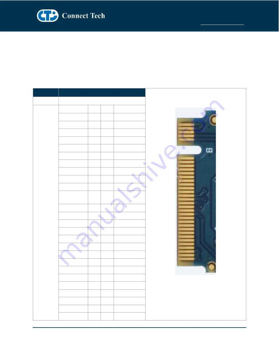
The M.2 GPS pin-out is compliant to the M.2 Socket 2 with B Key. This module uses only +3.3V for input
power and all I/O is +3.3V signaling.
Function
M.2 Card Edge Connector
Location
P3
Pinout
Signal
Pin Pin
Signal
NC
1
2
+3.3V
GND
3
4
+3.3V
GND
5
6
NC
USB_D+
7
8
W_DISABLE1#
USB_D-
9
10
NC
GND
11
12 Connector Key
Connector Key 13
14 Connector Key
Connector Key 15
16 Connector Key
Connector Key 17
18 Connector Key
Connector Key 19
20
NC
CONFIG_0
(GND)
21
22
NC
NC
23
24
NC
NC
25
26
NC
GND
27
28
NC
NC
29
30
NC
NC
31
32
NC
GND
33
34
NC
NC
35
36
NC
NC
37
38
NC
GND
39
40
M.2 GNSS SCL
NC
41
42 M.2 GNSS SDA
NC
43
44 M.2 GNSS IRQ
GND
45
46
NC
NC
47
48
NC
NC
49
50
RESET#
GND
51
52
NC


