16 Connectors/Pinouts
Xtreme/104 Opto User's Manual, ver. 0.00
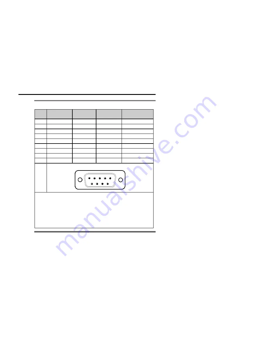
Table 4:
DB-9 cable connector pinouts
Pin
No.
RS-232
Signal
Direction
RS-485/422
Signal
Direction
1 NC
NC
RxD
(+) input
2 RxD
input
RxD
(-) input
3 TxD
output TxD
(+) output
4 NC
NC
TxD
(-) output
5
Isolated Gnd
signal gnd
Isolated Gnd
signal reference
6 NC
NC
CTS
(-) input
7 RTS
output RTS
(+) output
8 CTS
input
CTS
(+) input
9 NC
NC
RTS
(-) output
Male DB-9 Connector
1
5
6
9
Technical Tip:
1.
You must connect pin 5 (the isolated ground) to the
ground of the external device you are connecting to.
2.
Please ensure that you terminate the CTS signal if your
application does not use them. The common way to do this
is to connect CTS to RTS. Failure to do so may result in a
loss of a performance on your Xtreme/104 Opto adapter.
Summary of Contents for Xtreme 104 Opto
Page 2: ...Xtreme 104 Opto User s Manual ver 0 00 ...
Page 10: ...Xtreme 104 Opto User s Manual ver 0 00 ...
Page 16: ...Xtreme 104 Opto User s Manual ver 0 00 ...
Page 18: ...Xtreme 104 Opto User s Manual ver 0 00 ...
Page 24: ...Xtreme 104 Opto User s Manual ver 0 00 ...


