background image


Xtreme/GbE 24-Port - Managed Carrier Ethernet Switch  

Users Guide 

www.connecttech.com


Document: CTIM-00455 
Revision: 0.04 


Page 40 of 46 

Connect Tech Inc.  800-426-8979 | 519-836-1291


Date: 2017/08/04 


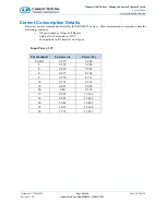
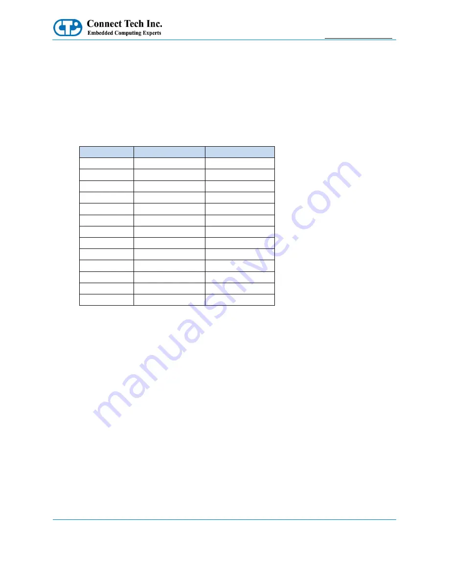
Current Consumption Details 

Below are current consumption details for the XDG024/25 devices.  These measurements were taken under the 
following conditions: 

o


All ports linked @ 1Gbps Full Duplex 

o


Ambient Air Temperature of 25°C 

o


Constant data traffic transfers on all ports 


Input Power: 12V 


Ports Linked 

Current (A) 

Power (W) 

0 (idle) 

0.537 

6.444 

0.583 

6.996 

0.629 

7.548 

0.677 

8.124 

0.726 

8.712 

10 

0.776 

9.312 

12 

0.827 

9.924 

14 

0.88 

10.56 

16 

0.932 

11.184 

18 

0.987 

11.844 

20 

1.041 

12.492 

22 

1.097 

13.164 

24 

1.151 

13.812 


Summary of Contents for Xtreme/GbE

Page 1: ... Toll 800 426 8979 North America only Guelph Ontario Fax 519 836 4878 N1K 1S6 Email sales connecttech com www connecttech com support connecttech com CTIM 00455 Revision 0 04 2017 08 04 Xtreme GbE 24 Port Managed Carrier Ethernet Switch Users Guide ...

Page 2: ...r 14 XDG025 Port Bank B Connector 15 XDG025 Port Bank C Connector 16 XDG025 Management Misc Connector 17 XDG025 Input Power Connector 18 XDG025 DIP Switch 19 XDG024 Detailed Feature Pinouts and Descriptions 20 XDG024 Port Bank A Connector 21 XDG024 Port Bank B Connector 22 XDG024 Port Bank C Connector 23 XDG024 Management Misc Connector 24 XDG024 Input Power Connector 25 XDG024 DIP Switch 26 CLI M...

Page 3: ...d 34 XBG002 XDG024 24 Port Vertical Breakout Board 35 XBG003 XDG024 24 Port Vertical Breakout Board 36 Board to Cable Details 37 Port LED Details 38 Thermal Details 39 XDG024 XDG025 Thermal Parameters 39 XHG102 XDG025 Conduction Cooled Heatplate 39 Current Consumption Details 40 Mechanical Details 41 3D STEP Models 41 2D Drawing XDG025 Connector Breakout Side 41 2D Drawing XDG025 Thermal Extractio...

Page 4: ...n assist you Our support section is available 24 hours a day 7 days a week on our website at www connecttech com sub support support asp See the contact information section below for more information on how to contact us directly Our technical support is always free Contact Information Mail Courier Connect Tech Inc Technical Support 42 Arrow Road Guelph Ontario Canada N1K 1S6 Email Internet sales ...

Page 5: ...which all components are available Should the product prove to be irreparable Connect Tech Inc reserves the right to substitute an equivalent product if available or to retract the Warranty if no replacement is available The above warranty is the only warranty authorized by Connect Tech Inc Under no circumstances will Connect Tech Inc be liable in any way for any damages including any lost profits...

Page 6: ...ntistatic packaging until they are ready to be installed Using a grounded wrist strap when handling circuit boards at a minimum you should touch a grounded metal object to dissipate any static charge that may be present on you Only handling circuit boards in ESD safe areas which may include ESD floor and table mats wrist strap stations and ESD safe lab coats Avoiding handling circuit boards in car...

Page 7: ...igh Density Board to Board Board to Cable Connectors Each High Density Connector Contains 8 Gigabit Ports Connectors can be mated directly to breakout boards or via cabling Power Management 2 x 2mm Pitch Locking Pin Headers Layer 2 Switching 802 1Q VLAN switch with 8K MACs and 4K VLANs Push pop up to two VLAN tags IPv4 IPv6 multicast Policing with storm control and MC BC protection RSTP and MSTP s...

Page 8: ...E 24 Port Managed Carrier Ethernet Switch Users Guide www connecttech com Document CTIM 00455 Revision 0 04 Page 8 of 46 Connect Tech Inc 800 426 8979 519 836 1291 Date 2017 08 04 Product Overview Block Diagram ...

Page 9: ...eatsinks that can be optionally installed XHG102 Conduction Cooled Heatplate for XDG025 DEV011 XDG025 Development Kit o XDG025 o XHG101 o 24 Port Development Breakout Board w LEDs o Development Board Sled o Universal AC DC Desktop Power Supply XBG001 24 Port RJ 45 Vertical Breakout Board XDG024 Only XBG002 8 Port Panel Mount RJ 45 Breakout Board requires CBG209 or CBG210 XBG003 8 Port Right Angle ...

Page 10: ...GbE 24 Port Managed Carrier Ethernet Switch Users Guide www connecttech com Document CTIM 00455 Revision 0 04 Page 10 of 46 Connect Tech Inc 800 426 8979 519 836 1291 Date 2017 08 04 Connector Locations XDG025 ...

Page 11: ...GbE 24 Port Managed Carrier Ethernet Switch Users Guide www connecttech com Document CTIM 00455 Revision 0 04 Page 11 of 46 Connect Tech Inc 800 426 8979 519 836 1291 Date 2017 08 04 Connector Locations XDG024 ...

Page 12: ...sc Serial LED Stream Reset Button and CLI Serial P7 Input Power 4V to 14V input P3A XDG024 Port Breakout Group A Ethernet Switch Ports 9 16 P3B XDG024 Port Breakout Group B Ethernet Switch Ports 5 8 17 20 P3C XDG024 Port Breakout Group C Ethernet Switch Ports 1 4 21 24 P4A XDG025 Port Breakout Group A Ethernet Switch Ports 9 16 P4B XDG025 Port Breakout Group B Ethernet Switch Ports 5 8 17 20 P4C X...

Page 13: ... Managed Carrier Ethernet Switch Users Guide www connecttech com Document CTIM 00455 Revision 0 04 Page 13 of 46 Connect Tech Inc 800 426 8979 519 836 1291 Date 2017 08 04 XDG025 Detailed Feature Pinouts and Descriptions ...

Page 14: ... 16 17 PORT9 GND PORT13 GND 18 19 PORT9 GND PORT13 GND 20 21 PORT10 D0_P PORT14 D0_P 22 23 PORT10 D0_N PORT14 D0_N 24 25 PORT10 D1_P PORT14 D1_P 26 27 PORT10 D1_N PORT14 D1_N 28 29 PORT10 D2_P PORT14 D2_P 30 31 PORT10 D2_N PORT14 D2_N 32 33 PORT10 D3_P PORT14 D3_P 34 35 PORT10 D3_N PORT14 D3_N 36 37 PORT10 GND PORT14 GND 38 39 PORT10 GND PORT14 GND 40 41 PORT11 GND PORT15 GND 42 43 PORT11 GND PORT...

Page 15: ... D3_N PORT20 D3_N 16 17 PORT5 GND PORT20 GND 18 19 PORT5 GND PORT20 GND 20 21 PORT6 D0_P PORT19 D0_P 22 23 PORT6 D0_N PORT19 D0_N 24 25 PORT6 D1_P PORT19 D1_P 26 27 PORT6 D1_N PORT19 D1_N 28 29 PORT6 D2_P PORT19 D2_P 30 31 PORT6 D2_N PORT19 D2_N 32 33 PORT6 D3_P PORT19 D3_P 34 35 PORT6 D3_N PORT19 D3_N 36 37 PORT6 GND PORT19 GND 38 39 PORT6 GND PORT19 GND 40 41 PORT7 GND PORT18 GND 42 43 PORT7 GND...

Page 16: ... D3_N PORT21 D3_N 16 17 PORT1 GND PORT21 GND 18 19 PORT1 GND PORT21 GND 20 21 PORT2 D0_P PORT22 D0_P 22 23 PORT2 D0_N PORT22 D0_N 24 25 PORT2 D1_P PORT22 D1_P 26 27 PORT2 D1_N PORT22 D1_N 28 29 PORT2 D2_P PORT22 D2_P 30 31 PORT2 D2_N PORT22 D2_N 32 33 PORT2 D3_P PORT22 D3_P 34 35 PORT2 D3_N PORT22 D3_N 36 37 PORT2 GND PORT22 GND 38 39 PORT2 GND PORT22 GND 40 41 PORT3 GND PORT23 GND 42 43 PORT3 GND...

Page 17: ...d Connector Manufacturer Samtec Part Number ESQT 105 02 L D XXX Mating Serial Cable CBG212 CTIC 00551 10 pin Minitek to DB 9 Male Pinout No Name Description 1 RESET_OUT 3 3V CMOS Reset Output Active Low 2 3 3V 3 3V output 2A max draw 3 RESET_BTN Reset Button Input Pulse Low to initiate switch software reset 4 GND Ground Connection 5 LED_PWM Serial LED Stream PWM Output 6 LED_DO Serial LED Stream D...

Page 18: ...n P7 XDG025 Connector Manufacturer FCI Part Number 98414 G06 06LF Mating Cable Connector Manufacturer FCI Part Number 10073599 006LF Mating Board to Board Connector Manufacturer Samtec Part Number ESQT 103 02 L D XXX Mating Power Cable CBG213 CTIC 00552 6 pin Minitek to Flying Leads Pinout No Name Description 1 VIN VIN Power Input 5V to 12V 2 VIN VIN Power Input 5V to 12V 3 GND Ground Input 4 VIN ...

Page 19: ...sition DIP switch This DIP can be left in its default shipping orientation for normal operation However details on the switch positions and their functionality can be found below Position No Position Description Switch ON Switch OFF 1 A Manual Reset Selection Hold Device In Reset Normal Operation 2 B CLI Serial Selection CLI to External P5 N A DIP Switch Usage Examples Normal Operation CLI to Exte...

Page 20: ... Managed Carrier Ethernet Switch Users Guide www connecttech com Document CTIM 00455 Revision 0 04 Page 20 of 46 Connect Tech Inc 800 426 8979 519 836 1291 Date 2017 08 04 XDG024 Detailed Feature Pinouts and Descriptions ...

Page 21: ... 17 PORT13 GND PORT9 GND 18 19 PORT13 GND PORT9 GND 20 21 PORT14 D0_P PORT10 D0_P 22 23 PORT14 D0_N PORT10 D0_N 24 25 PORT14 D1_P PORT10 D1_P 26 27 PORT14 D1_N PORT10 D1_N 28 29 PORT14 D2_P PORT10 D2_P 30 31 PORT14 D2_N PORT10 D2_N 32 33 PORT14 D3_P PORT10 D3_P 34 35 PORT14 D3_N PORT10 D3_N 36 37 PORT14 GND PORT10 GND 38 39 PORT14 GND PORT10 GND 40 41 PORT15 GND PORT11 GND 42 43 PORT15 GND PORT11 ...

Page 22: ...3_N PORT5 D3_N 16 17 PORT20 GND PORT5 GND 18 19 PORT20 GND PORT5 GND 20 21 PORT19 D0_P PORT6 D0_P 22 23 PORT19 D0_N PORT6 D0_N 24 25 PORT19 D1_P PORT6 D1_P 26 27 PORT19 D1_N PORT6 D1_N 28 29 PORT19 D2_P PORT6 D2_P 30 31 PORT19 D2_N PORT6 D2_N 32 33 PORT19 D3_P PORT6 D3_P 34 35 PORT19 D3_N PORT6 D3_N 36 37 PORT19 GND PORT6 GND 38 39 PORT19 GND PORT6 GND 40 41 PORT18 GND PORT7 GND 42 43 PORT18 GND P...

Page 23: ...3_N PORT1 D3_N 16 17 PORT21 GND PORT1 GND 18 19 PORT21 GND PORT1 GND 20 21 PORT22 D0_P PORT2 D0_P 22 23 PORT22 D0_N PORT2 D0_N 24 25 PORT22 D1_P PORT2 D1_P 26 27 PORT22 D1_N PORT2 D1_N 28 29 PORT22 D2_P PORT2 D2_P 30 31 PORT22 D2_N PORT2 D2_N 32 33 PORT22 D3_P PORT2 D3_P 34 35 PORT22 D3_N PORT2 D3_N 36 37 PORT22 GND PORT2 GND 38 39 PORT22 GND PORT2 GND 40 41 PORT23 GND PORT3 GND 42 43 PORT23 GND P...

Page 24: ...Part Number 10073599 010LF Mating Serial Cable CBG202 CTIC 00549 10 pin Minitek to DB 9 Male Pinout No Name Description 1 RS232 TX CLI Serial Management Interface RS 232 TX line output 2 RS232 RX CLI Serial Management Interface RS 232 RX line input 3 LED_CLK Serial LED Stream Clock Output 4 LED_LD Serial LED Stream Load Output 5 LED_PWM Serial LED Stream PWM Output 6 LED_DO Serial LED Stream Data ...

Page 25: ...Main Input Power Connector For XDG024 Only Location P7 XDG025 Connector Manufacturer FCI Part Number 98414 G06 06LF Mating Cable Connector Manufacturer FCI Part Number 10073599 006LF Mating Power Cable CBG112 CTIC 00431 6 pin Minitek to Flying Leads Pinout No Name Description 1 GND Ground Input 2 GND Ground Input 3 GND Ground Input 4 VIN VIN Power Input 5V to 12V 5 VIN VIN Power Input 5V to 12V 6 ...

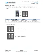
Page 26: ...h This DIP can be left in its default shipping orientation for normal operation However details on the switch positions and their functionality can be found below Position No Position Description Switch ON Switch OFF 1 A Manual Reset Selection Hold Device In Reset Normal Operation 2 B CLI Serial Connection CLI to PCIe 104 Bus PCIe UART CLI to External P5 Connector DIP Switch Usage Examples Normal ...

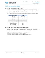
Page 27: ...o parity Note the XDG external serial port is compatible with RS 232 Input Output Levels NOT TTL or CMOS RS 232 Serial Parameter Value Baud Rate 115200 bps Data Bits 8 Parity None Stop Bit 1 Output Voltage Swing 4 2 V Input Voltage Range 15 V Input Threshold Low 0 8 V Input Threshold High 2 4 V CLI Access via PCIe 104 Bus XDG024 Model Only The XDG024 product connects to the CLI management interfac...

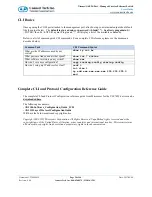
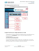
Page 28: ...nt br What ports are linked and at what speed show int status What software version is on my switch show ver How do I save my configuration copy running config startup config How do I setup my IP address for vlan1 conf t int vlan 1 ip add xxx xxx xxx xxx 255 255 255 0 end Complete CLI and Protocol Configuration Reference Guide The complete CLI and Protocol Configuration reference guide from Micros...

Page 29: ...me GbE to your host PC using a standard Cat5e ethernet cable o Setup your host PC s IP address to be on the same subnet as Xtreme GbE 192 168 42 X o Open a web browser and go to the 192 168 42 1 address o Now you should see the login screen and from here you can setup the Xtreme GbE to an IP address on your network Method 2 Changing the Xtreme GbE IP to one on your network via the CLI This method ...

Page 30: ...guration reference guide from Microsemi for the VSC7429 device can be downloaded here It will have CLI and Web configuration methods listed The following document AN1115Layer2ProtocolConfigurationGuide Will have the below mentioned copyright notice Copyright 2002 2015 Microsemi Corporation All Rights Reserved Unpublished rights reserved under the copyright laws of the United States of America othe...

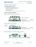
Page 31: ... power supplies are off 2 Connect any Breakout Boards or external port cabling 3 Ensure voltage is in the range of 4V to 14V 4 Turn on external power supply 5 XDG will now boot up 6 It will default to an unmanaged mode where all ports are switched to all ports XDG025 Standalone Application XDG025 mated with Breakout Board with Vertical Connectors XDG025 mated with Board to Cable Assemblies XDG025 ...

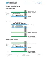
Page 32: ... Guide www connecttech com Document CTIM 00455 Revision 0 04 Page 32 of 46 Connect Tech Inc 800 426 8979 519 836 1291 Date 2017 08 04 XDG024 In Stack PCIe 104 Bottom Stacking Application Top Stacking Application Use Case 1 Top Stacking Application Use Case 2 ...

Page 33: ...reakout Board If a user wishes to create their own custom breakout board to connect directly to the XDG or from cabling off of the XDG Connect Tech has prepared a simple reference design package that can be downloaded below Connect Tech also offers quick turn low cost custom breakout design services for more information on this contact sales connecttech com XDG025 Breakout Stacking Reference Desig...

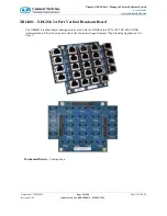
Page 34: ...Connect Tech Inc 800 426 8979 519 836 1291 Date 2017 08 04 XBG001 XDG024 24 Port Vertical Breakout Board The XBG001 breakout board is designed to be used with the XDG024 in a PCIe 104 TOP STACKING implementation This is shown above the in the Hardware Usage Example Top Stacking Application Use Case 1 Mechanical Details Coming Soon ...

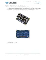
Page 35: ...e 2017 08 04 XBG002 XDG024 24 Port Vertical Breakout Board The XBG002 is vertical panel mounted breakout board that can be connected to the XDG024 with the CBG209 breakout cable or to the XDG025 with the CBG210 breakout cable The intended use is to be mounted directly to a chassis or IO panel with standoffs in the 4 corner mounting hole locations Mechanical Details Coming Soon ...

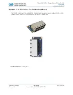
Page 36: ...ge 36 of 46 Connect Tech Inc 800 426 8979 519 836 1291 Date 2017 08 04 XBG003 XDG024 24 Port Vertical Breakout Board The XBG003 is right angle 2x4 stacked RJ 45 breakout board that can be connected to the XDG024 with the CBG209 breakout cable or to the XDG025 with the CBG210 breakout cable Mechanical Details Coming Soon ...

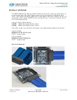
Page 37: ...s system These cables use the Samtec HQDP which is a High Speed Twinax Cable Assembly The uses a 40 pair grouping so that 8 ports per HQDP cable can be broken out at once Please refer to the pinout sections above for pin mapping details Connect Tech has 2 standard offerings CBG209 XDG024 8inch Breakout Cable 8 Ports CBG210 XDG025 8inch Breakout Cable 8 Ports These cables can also be sourced direct...

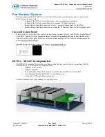
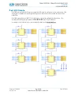
Page 38: ...to output the LED status for each port as well as system status This serial signal is intended to be run through shift registers as shown below to de serialize the stream Each output from The XDG requires the use of QTY 7 8 bit shift registers setup in the configuration shown below The recommended shift register part number is SN74AHC595PW from Texas Instruments An example circuit is shown below o...

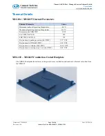
Page 39: ...ient Operating Temperature 40 C Maximum Operating Junction Temperature 125 C Recommended XDG TDP 15W SoC TDP VSC7429 8W PHY TDP VSC8512 7W Die junction to package case top SoC PHY 3 27 C W Die junction to PCB SoC PHY 6 03 C W Die junction to Ambient SoC PHY 12 14 C W Die junction to moving air 1 m s SoC PHY 9 42 C W XHG102 XDG025 Conduction Cooled Heatplate The XHG102 heatplate shown below is desi...

Page 40: ...ils for the XDG024 25 devices These measurements were taken under the following conditions o All ports linked 1Gbps Full Duplex o Ambient Air Temperature of 25 C o Constant data traffic transfers on all ports Input Power 12V Ports Linked Current A Power W 0 idle 0 537 6 444 2 0 583 6 996 4 0 629 7 548 6 0 677 8 124 8 0 726 8 712 10 0 776 9 312 12 0 827 9 924 14 0 88 10 56 16 0 932 11 184 18 0 987 ...

Page 41: ...0 426 8979 519 836 1291 Date 2017 08 04 Mechanical Details 3D STEP Models A complete 3D STEP Model file of COM Express Type 6 104e Carrier can be downloaded here http www connecttech com ftp 3d_models XDG024 25_3D_MODEL zip 2D Mechanical Dimensioned Drawing Top View PCB and Mounting Hole Dimension are in mil 2D Drawing XDG025 Connector Breakout Side ...

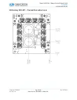
Page 42: ...ort Managed Carrier Ethernet Switch Users Guide www connecttech com Document CTIM 00455 Revision 0 04 Page 42 of 46 Connect Tech Inc 800 426 8979 519 836 1291 Date 2017 08 04 2D Drawing XDG025 Thermal Extraction Layer ...

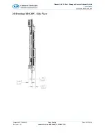
Page 43: ...bE 24 Port Managed Carrier Ethernet Switch Users Guide www connecttech com Document CTIM 00455 Revision 0 04 Page 43 of 46 Connect Tech Inc 800 426 8979 519 836 1291 Date 2017 08 04 2D Drawing XDG025 Side View ...

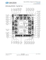
Page 44: ... 24 Port Managed Carrier Ethernet Switch Users Guide www connecttech com Document CTIM 00455 Revision 0 04 Page 44 of 46 Connect Tech Inc 800 426 8979 519 836 1291 Date 2017 08 04 2D Drawing XDG024 Top Side View ...

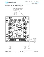
Page 45: ...24 Port Managed Carrier Ethernet Switch Users Guide www connecttech com Document CTIM 00455 Revision 0 04 Page 45 of 46 Connect Tech Inc 800 426 8979 519 836 1291 Date 2017 08 04 2D Drawing XDG024 Bottom Side View ...

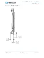
Page 46: ...bE 24 Port Managed Carrier Ethernet Switch Users Guide www connecttech com Document CTIM 00455 Revision 0 04 Page 46 of 46 Connect Tech Inc 800 426 8979 519 836 1291 Date 2017 08 04 2D Drawing XDG024 Side View ...

Reviews: