


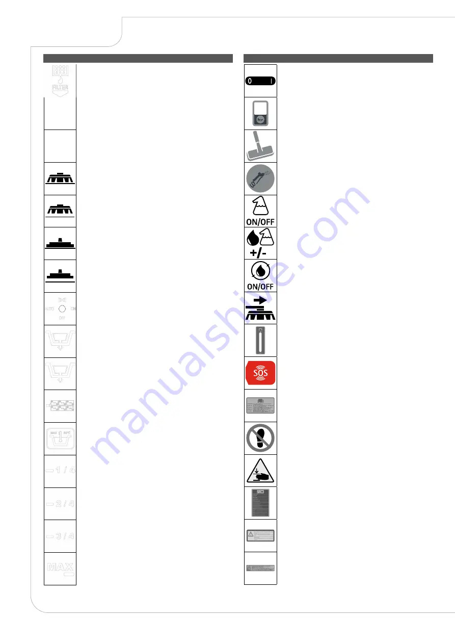
SYMBOLS USED ON THE MACHINE
LABELS USED ON THE MACHINE
14
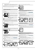
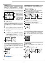
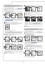
Filter body position symbol:
Applied to the left-hand side of the machine to indicate the position of the solution
tank's filter.
P
Extra pressure activation/deactivation lever position symbol:
Applied to the central brush head's extra pressure activation/deactivation lever.
R
Reverse gear activation/deactivation lever position symbol:
Applied to the reverse gear activation/deactivation lever.
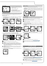
Brush head body working position symbol:
Applied to the steering column to indicate the brush head control lever direction of
rotation for bringing the brushes to their working position.
Brush head body standby position symbol:
Applied to the steering column to indicate the brush head control lever direction of
rotation for bringing the brushes to their standby position.
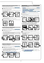
Squeegee body working position symbol:
Applied to the steering column to indicate the squeegee control lever direction of
rotation for bringing the squeegee to its working position.
Squeegee body standby position symbol:
Applied to the steering column to indicate the squeegee control lever direction of
rotation for bringing the squeegee to its standby position.
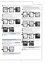
Symbol for activation/deactivation of the blinking lights:
Applied to the front of the machine, to indicate the blinking lights switch.
Recovery tank drainage hose symbol:
Applied to the back of the machine to identify the recovery tank's drainage hose.
Solution tank drainage cap symbol:
Applied to the back of the machine to identify the solution tank's drainage cap.
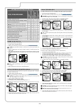
Battery connection symbol:
Applied beneath the recovery tank to indicate how to connect the 6V or 18V
batteries in order to obtain a total voltage of 36V.
Symbol for maximum temperature for filling the solution tank:
Applied to the left-hand side of the machine's solution tank to indicate the
maximum temperature of the water that can be used to safely fill the solution tank.
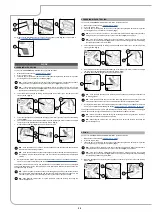
Solution tank filling symbol:
Located on the left side of the machine's solution tank to indicate the amount of
water or detergent solution in the tank. The symbol on the side indicates that the
tank is full to about a quarter of its capacity.
Solution tank filling symbol:
Located on the left side of the machine's solution tank to indicate the amount of
water or detergent solution in the tank. The symbol on the side indicates that the
tank is full to about a half of its capacity.
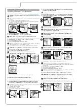
Solution tank filling symbol:
Located on the left side of the machine's solution tank to indicate the amount of
water or detergent solution in the tank. The symbol on the side indicates that the
tank is full to about three-quarters of its capacity.
Solution tank filling symbol:
Located on the left side of the machine's solution tank to indicate the amount of
water or detergent solution in the tank. The symbol on the side indicates that the
tank is full.
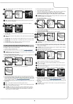
Main switch symbol:
Applied to the control panel, positioned on the front of the machine, to indicate
the main switch.
Acoustic signalling device control label:
Applied in the vicinity of the steering column to indicate the acoustic signalling
device's control button.
Vacuum wand control label (optional):
Applied near the steering column to indicate the control button for the optional
vacuum wand kit.
Spray gun control label (optional):
Applied near the steering column to indicate the control button for the optional
spray gun kit.
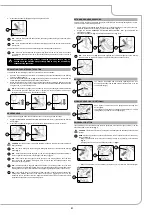
Label for the automatic detergent dosing system (optional):
Applied near the steering column to indicate the button for activating or switching
off the optional detergent dosing system.
Label for adjusting the automatic detergent dosing system (optional):
Applied near the steering column to indicate the button for adjusting the automatic
detergent dosing system.
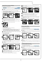
Label for the detergent solution automatic recycling system control
(optional):
Applied near the steering column to indicate the button for activating or switching
off the optional detergent solution automatic recycling system kit.
Label for the side brush control (optional):
Applied near the steering column to indicate the button for activating or switching
off the side brush control system.
Label for detergent solution tap command:
Applied in the vicinity of the control column to identify the detergent solution tap's
control lever.
FFM alarm activation label (optional):
Applied in the vicinity of the emergency mushroom button, to identify the button
activating a request for assistance.
Label indicating the need to read the Use and Maintenance Manual:
Applied in the vicinity of the steering column in order to remind the operator to
read the user and maintenance manual before using the machine.
Treading ban label:
Located on the machine, to identify the surfaces that must not be trodden on (risk
of personal injury or damage to the machine).
Label warning about the risk of crushed hands:
Indicates danger to hands due to crushing between two surfaces.
Warning label:
Affixed to the machine in order to warn the operator to read the user and
maintenance manual (this document) before using the machine for the first time.
Also indicates the applicable procedures for properly caring for the machine itself.
Solution tank filter daily care warning label:
Applied to the machine to remind the operator to clean the solution tank after
each use.
Vacuum motor filter label:
Applied inside the vacuum cover to identify the vacuum motor intake air filter, and
also serves to remind the operator to clean the filter after each machine use.


