


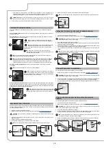
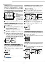
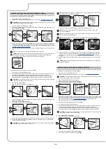
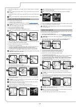


5. Press the drive pedal (4) (
Fig.4
) to begin moving the machine.
N.B.
: Once the drive pedal has been pressed, the squeegee body will begin to descend into its
working position.
N.B.
: Once the squeegee body has reached its working position, the vacuum motor will enter
into function.
The machine will now work at its maximum efficiency level until the batteries run down.
N.B.
: If the drive pedal is released during the drying operation, the vacuum motor will continue
to operate for a few seconds in order to ensure that all the liquid present in the vacuum hose is
extracted.
ATTENTION: The drying without scrubbing operation should only be
carried out if the machine was previously used to carry out a scrubbing
without drying operation.
4
4
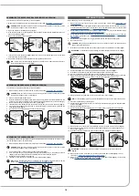
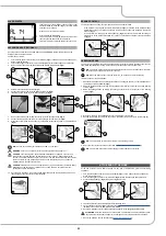
REGULATING THE DETERGENT SOLUTION
To adjust the amount of detergent solution on the brush, proceed as follows:
1.
Open the tap's output flow to maximum, and shift the knob on the left hand side of the steering
column (1) (
Fig.1
) upward.
2. When the drive pedal is pressed (2) (
Fig.2
), the brush gear motors will enter into function and the
solenoid valve will distribute detergent solution to the brushes.
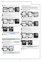
3.
During the first few metres, check to make sure that the quantity of solution is sufficient to wet the
floor, but not so much as to come out of the splash guard. The detergent leakage can be adjusted
using the knob (1) on the steering column.
N.B.
: When the knob (1)
(
Fig.1
)
is moved upwards, the amount of detergent solution distributed
to the brushes increases. When the knob (1)
(
Fig.3
)
is moved downwards, the amount of
detergent solution distributed to the brushes decreases.
3
2
1
1
1
2
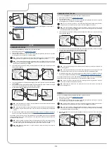
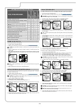
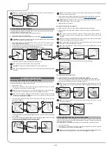
REVERSE GEAR
This machine is equipped with electronic traction control. To reverse, proceed as follows:
1. Engage the “REVERSE GEAR ACTIVATION/DEACTIVATION” lever (1) underneath the steering
wheel (
Fig.1
).
2. Press the drive pedal (2) (
Fig.2
); in this manner the machine will begin to move in reverse.
CAUTION
: the reverse speed is lower than the forward speed to comply with current health and
safety standards.
N.B.
: In order to disengage the reverse gear, disengage the lever (1) underneath the steering
wheel (
Fig.1
).
N.B.
: Once the lever has been engaged (1), the acoustic signalling device will be activated in
order to signal that the machine's reverse gear has been engaged.
N.B.
: If the reverse gear is engaged with the squeegee in its working position, once the drive
pedal is pressed, the machine will begin to move in reverse and the squeegee body will be
raised into its resting position.
N.B.
: If the reverse gear is engaged with the brush head in its working position, once the drive
pedal is pressed, the machine will begin to move in reverse and the brush head will remain in its
working position, but the solenoid valve will stop dispensing detergent solution to the brushes.
N.B.
: if you reverse using the anti-collision system (optional) a special function activates that
manages the ON/OFF frequency of the buzzer. Every 50ms a trigger signal is sent to the
ultrasound sensor, the sensor returns a signal that remains active for a period that is inversely
proportional to the distance of the reflecting object.
2
1
1
2
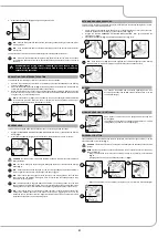
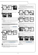
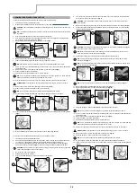
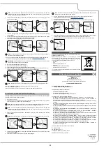
EXTRA BRUSH HEAD PRESSURE
This machine is capable of increasing the pressure exerted upon the brushes during the work cycle.
This can be done in the following manner:
1.
Check to make sure that the brush head body is in contact with the floor. If this is not the case,
adjust the brush head control lever (1) on the steering column (
Fig.1
).
2. Engage the “EXTRA-PRESSURE ACTIVATION/DEACTIVATION” lever (2) underneath the
steering wheel (
Fig.2
).
3. Press the drive pedal (3) (
Fig.3
) to initiate the machine's working cycle.
N.B.
: Once the lever (2) (
Fig.4
) has been engaged, the red indicator light (4) on the steering
column will turn on to indicate that the extra-pressure function has been enabled.
2
3
1
1
2
3
4
4
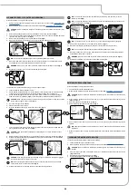
BUZZER
The machine is equipped with an acoustic signalling device. If an
acoustic signal needs to be emitted, simply press the button (1) on the
control panel (
Fig.1
).
1
1
WORKING HEADLIGHTS (OPTIONAL)
Upon request, the machine can be equipped with front and rear
working lights.
These lights can be turned on by setting the main switch to “I”, namely
turning the key a quarter turn to the right (
Fig.1
).
1
ON
1
EMERGENCY BUTTON
If any problems are encountered during the work operations, press the emergency button (1) on the
electrical system's cover carter (
Fig.1
).
CAUTION
: This command interrupts the electrical circuit between the batteries and the machine
system.
NOTE
: After having stopped and resolved the problem, the work operations can be resumed by
doing the following:
•
Bring the main switch to its "0" position by turning the key (2) a quarter turn anti-clockwise
(
Fig.2
).
• Disengage the mushroom-head emergency button (1) (
Fig.3
).
•
Bring the main switch to its "I" position by turning the key (2) a quarter turn clockwise (
Fig.4
).
1
3
1
1
2
2
OFF
4
2
ON
21


