


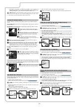
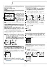
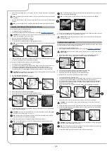


HOUR METER
The control display is located on the control panel, and the screen that appears after the start-up screen
displays the machine's total usage time.
The numbers before the "." symbol identify hours, while the number that follows it indicates hour
decimals (an hour decimal corresponds to six minutes).
When the “hour glass” symbol (1) is flashing it indicates that the hour meter is counting the appliance's
operating time.
BATTERY CHARGE LEVEL INDICATOR
The control panel is equipped with a control display.
The graphic symbol that identifies the charge level of batteries appears at the bottom of the control
display.
The indicator consists of charge level
symbols (2).
When the minimum remaining charge
is reached, the graphic symbol (2) will
start to blink, and will turn off after a few
seconds, after which the symbol (3) will
start to blink. Under these conditions,
the machine must be brought to the
battery charging area.
N.B.
: A few seconds after the battery
charge reaches the critical level (2), the
brush gear motors will shut off
automatically. With the remaining
charge it is possible to complete the
drying process before starting the
recharge.
N.B.
: A few seconds after the battery charge level reaches the discharge level (2), the vacuum
motor switches off automatically.
1
2
3
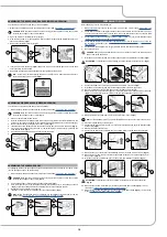
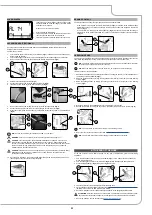
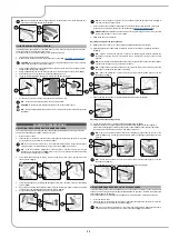
ACTIVATING THE SIDE BRUSH (VERSION 1SL OR 2SL)
If the lateral brush needs to be used during the floor scrubbing operations, and therefore with the brush
head in its working position, press the lateral brush head activation/deactivation button (1) on the left-
hand side of the steering column (
Fig.1
).
N.B.
: When the lateral brush is in function, the LED indicator light inside the button (1) will be on.
N.B.
: By pressing the button (1), the side brush head will begin to move towards the outside of
the machine, and the solenoid valve will only begin to dispense the detergent solution once it has
reached its working position (valid only for scrubbing versions).
By pressing the button (1) the side brushes will start to move towards the floor and the gear
motors of the side brushes will start to work (valid only for sweeping versions).
N.B.
: In order to bring the side brush head back to its resting position, press the button (1) (valid
only for scrubbing versions).
In order to bring the side brushes back to their resting positions, press the button (1) (valid only
for sweeping versions).
N.B.
: If the central brush head is raised with the lateral brush head in its working position, the
lever (2) on the steering column (
Fig.2
) can be turned in order to bring the lateral brush head
back to its resting position as well. The LED indicator inside the button (1) will nevertheless
remain on to indicate that if the central brush head is brought back to its working position, the
side one will move to the right (valid only for scrubbing versions).
If the central brush head is raised with the side brush head in its working position, by turning the
lever (2) on the steering column (
Fig.2
) also the side brushes can be brought back to the resting
position. The LED indicator inside the button (1) will nevertheless remain on to indicate that if the
central brush head is brought back to its working position, also the side brushes will be brought
into contact with the floor (valid only for scrubbing versions).
2
1
1
2
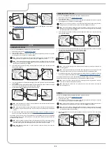
ACTIVATING DETERGENT SOLUTION RECYCLING (FLR VERSION)
Upon request the machine can be fitted with a system that allows the detergent solution to be recycled
so that productivity can be increased, since the number of stops needed to empty and fill the tanks is
reduced. As a result less water and detergent are used, thereby making the operator safer, who comes
into contact with the chemical products less frequently, and the operation is more environmentally
friendly.
If the machine being used features the system for recycling the detergent solution, once the machine
has been started up, press the FLR system activation - deactivation button (1), on the left side of the
steering column (
Fig.1
). Once the work operations have been completed, remember to shut off the FLR
system by pressing the button (1).
N.B.
: When the FLR system is in function, the LED indicator light inside the button (1) will be on.
N.B.
: At the end of the workday, perform
all the procedures listed in the “
1
1
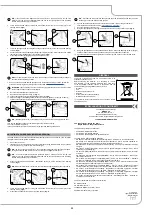
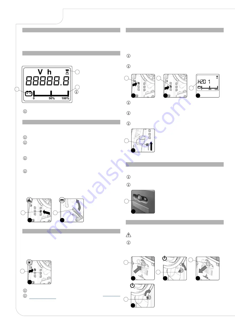
AUTOMATIC DETERGENT MEASURING SYSTEM (FSS VERSION)
Upon request, the machine can be fitted with a system that measures out the detergent separately
from the water in the solution tank. To start it do as follows.
1. Once the machine has been started up, press the FSS system activation - deactivation button (1)
(
Fig.1
) on the left side of the steering column.
2. Press the detergent solution adjustment button (2), on the left side of the steering column, to
select the level you want to use for the task in hand (
Fig.2
).
N.B.
: If you press the button (2) (
Fig.2
), the control display will show a code indicating the
amount of detergent in the machine's water system. Press the button gradually to cyclically
alter the amount of detergent; there are four possible settings (from 0 to 3).
N.B.
: If the command display shows the code H2O 0, the machine doesn't dispense detergent
(
Fig.3
). This mode is used when the floor is already wet or in general when the chemical action
of water and detergent solution is not necessary.
N.B.
: With each press of the button (2), the amount of solution released into the machine water
system will increase by one level. Once the maximum level has been reached, a further press
on the button will return you to level 0 (no solution dispensed).
N.B.
: Passing from one step to another is a continuous cycle - it is not possible to go back
except by continuing to the end of the scale and starting again from zero. If the machine is
switched off via the main switch, the flow of detergent will return to step -03.
N.B.
: If this system is used, the water adjustment tap must always be at its maximum setting,
move the knob (4) upwards (
Fig.4
).
3
1
2
1
2
3
4
4
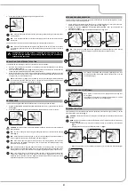
AUTOMATIC REQUEST FOR TECHNICAL ASSISTANCE (OPTIONAL) 24
The machine has an automatic service for activating an urgent technical assistance request. To activate
this function, the operator only has to press the button under the hatch (1) bearing the symbol “SOS”.
N.B.
: in order to activate this urgent technical assistance request the machine needs to be
equipped with the FIMAP FLEET MANAGEMENT kit.
N.B.
: in order to send a technical assistance request the machine needs to be on and should be
in a zone with data traffic coverage.
1
1
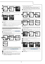
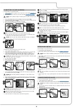
EMERGENCY BUTTON
If any serious problems are encountered during the work operations, press the emergency button (1)
on the electrical system's carter (
Fig.1
).
CAUTION
: This command interrupts the electrical circuit between the batteries and the machine
system.
N.B.
: After having stopped and resolved the problem, the work operations can be resumed by
doing the following:
• Set the main machine switch to “0” (
Fig.2
).
• Disengage the mushroom-head emergency button (1) (
Fig.3
).
• Set the main switch to "I" (
Fig.4
).
1
3
1
1
2
4
2
2
OFF
ON
22


