


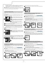
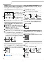
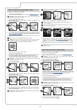
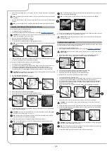


CLEANING THE RECYCLE FILTER (FLR VERSIONS)
Proceed as follows to empty the recovery tank:
1. Perform the procedure for emptying the recovery tank (see the section titled “
”).
2. Make sure the machine has been secured (see the section titled “
CAUTION
: users are advised to always wear protective gloves, to avoid the risk of serious injury
to hands.
3. With the tank empty, grip the handles (1) moulded on the recovery tank cover (
Fig.1
).
4.
Turn the recovery tank cover until the support (2) fixed to the recovery tank is coupled with the pin
(3) fixed to the recovery tank cover (
Fig.2
).
5.
Remove the recycle filter (4), only valid for FLR versions (
Fig.3
).
6.
Rinse the recycle filter (4) thoroughly under the jet of the tank cleaning accessory.
N.B.
: Use a spatula to eliminate any dirt that is particularly difficult to remove.
7. Rinse the inside of the recovery tank with a jet of water. If necessary, use a spatula to remove
any sludge that may have accumulated at the bottom of the tank.
WARNING
: Make sure to also clean the electric-mechanical float (5) inside the tank (
Fig.4
).
8. Repeat the operations in reverse order to reassemble all the parts.
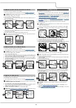
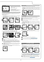
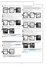
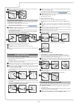
To clean the recovery tank with the spray gun kit, proceed as follows:
1. Take the machine to the maintenance area.
2. Check that the brush head body is in its rest position. If this is not the case, turn the brush head
control lever (1) anticlockwise (
Fig.1
) so that the brush head body lifts up off the floor.
3. Check that the squeegee body is in its rest position. If this is not the case, turn the squeegee
head control lever (1) clockwise (
Fig.2
), so that the squeegee head body lifts up off the floor.
CAUTION
: these operations must be carried out using protective gloves to avoid any possible
contact with the edges or tips of metal objects.
4. Go to the front right of the machine.
5. Stand at the back of the machine.
6. Grip the moulded handles (3) on the recovery tank cover (
Fig.3
).
7.
Turn the recovery tank cover until the support (4) fixed to the recovery tank is coupled with the
pin (5) fixed to the recovery tank cover (
Fig.4
).
CAUTION
: users are advised to always wear protective gloves, to avoid the risk of serious
injury to hands.
8. Release the tank cleaning accessory (6) (at the back of the machine) from the retainers (
Fig.5
).
9. Activate the optional tank cleaning kit ON/OFF pump by pressing the button (7) on the steering
column of the machine (
Fig.6
).
CAUTION
: when using the optional tank cleaning kit, you are advised to always wear goggles
to avoid any risk of serious injury to your eyes.
N.B.
: Before starting the optional tank cleaning kit, check the level indicator (8) to see how
much solution there is in the solution tank (
Fig.8
).
10. Activate the solution jet by pressing the lever in the tank cleaning accessory.
3
4
2
1
1
2
3
4
5
3
1
2
1
2
3
4
4
5
5
6
6
7
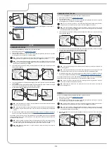
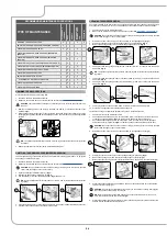
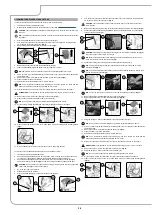
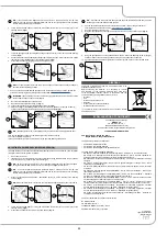
N.B.
: To adjust the solution jet from the
tank cleaning accessory, turn the knob (9) on the
accessory itself
(
Fig.8
).
N.B.
: To adjust the intensity of the solution jet from the
tank cleaning accessory, turn the knob
(10) on the accessory itself
(
Fig.9
).
N.B.
: To stop the solution jet,
use the lever (11) on the tank cleaning accessory (
Fig.10
).
11.
Remove the recycle filter (12), only valid for FLR versions (
Fig.11
).
12.
Rinse the recycle filter (12) thoroughly under the jet of the tank cleaning accessory.
N.B.
: Use a spatula to eliminate any dirt that is particularly difficult to remove.
13. Rinse the inside of the recovery tank, if necessary use a spatula to remove the sludge that has
accumulated at the bottom of the tank.
WARNING
: Be sure to also clean the electro-mechanical float (13) inside the tank (
Fig.12
).
14. Repeat the operations in reverse order to reassemble all the parts.
9
10
8
9
7
8
12
13
11
10
11
12
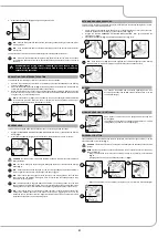
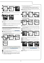
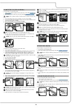
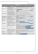
EMPTYING THE SOLUTION TANK
Proceed as follows to empty the solution tank:
1. Take the machine to the maintenance area.
2. Make sure the machine has been secured (see the section titled “
”).
CAUTION
: users are advised to always wear protective gloves, to avoid the risk of serious injury
to hands.
3.
Close the tap's output flow, and shift the knob (1) on the left hand side of the steering column
(
Fig.1
) downward.
4. Open the machine's left lateral hatch (2) (
Fig.2
).
5.
Remove the detergent solution filter cap (3) (
Fig.3
).
6.
Open the tap's output flow, and shift the knob (1) on the left hand side of the steering column
upward.
N.B.
: the place designated for this operation must comply with current environmental protection
regulations.
7. When the solution tank is empty, repeat the operations in the reverse order to reassemble all the
parts.
2
3
1
1
2
3
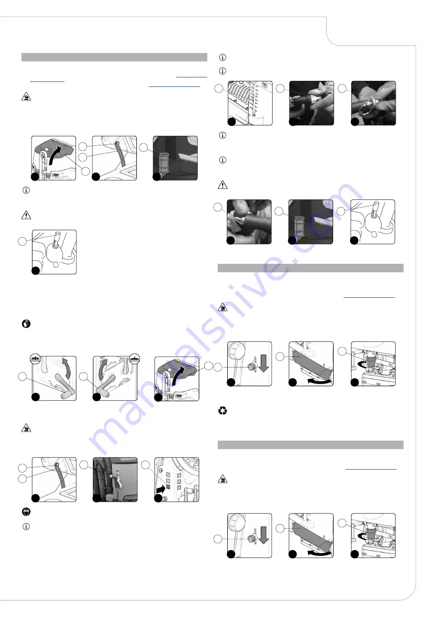
CLEANING THE WATER SYSTEM FILTER
In order to clean the water system's filter, do the following:
1. Take the machine to the maintenance area.
2. Make sure the machine has been secured (see the section titled “
”).
CAUTION
: users are advised to always wear protective gloves, to avoid the risk of serious injury
to hands.
3.
Close the tap's output flow, and shift the knob (1) on the left hand side of the steering column
(
Fig.1
) downward.
4. Open the machine's left lateral hatch (2) (
Fig.2
).
5.
Unscrew the detergent solution filter cap (3) (
Fig.3
).
2
3
1
1
2
3
29


