N.B.
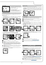
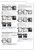
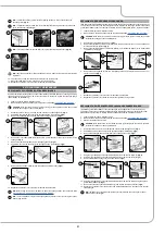
: If the control board's diagnostics procedure returns a positive outcome, the red LED
indicator (2) on the control panel (
Fig.2
) will turn off, and an acoustic signal will sound indicating
that the work operations may be initiated.
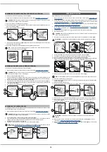
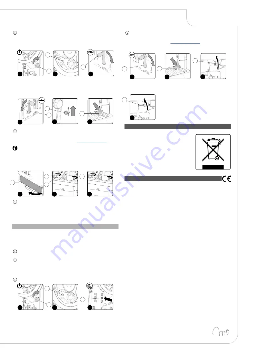
3. Lower the brush head body by turning the brush head control lever (3) on the rear part of the
steering column (
Fig.3
).
4. Lower the squeegee body by turning the squeegee control lever (4) on the rear part of the steering
column (
Fig.4
).
5. Check to make sure that the detergent solution tap is completely open. If this is not the case, adjust
the lever (5) on the left-hand side of the steering column (
Fig.5
).
6. Press the drive pedal (6) (
Fig.6
) to begin moving the machine.
NB
: Once the drive pedal is pressed, the brush head body and the squeegee body will begin to
descend into their working positions.
7. As soon as the brush head and the squeegee have reached their working positions, perform the
procedure for securing the machine (see the section titled “
ATTENTION
: these operations must be carried out using protective gloves to avoid any possible
contact with the edges or tips of metal objects.
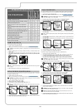
8. Go to the front left-hand side of the machine.
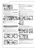
9. Open the machine's left side casing (7) (
Fig.7
).
10. Loosen the retention nuts (8) of the adjusting screws (9) (
Fig.0
).
11.
Adjust the height of the splash guard with respect to the floor, tighten or loosen the screws (9)
until the splash guard just touches the floor along its entire length (
Fig.9
).
N.B.
: Both the front and rear of the splash guard need to be at the same height off the floor.
12. Once the adjustment has been completed, tighten the retention nuts (8).
13. Close the left lateral carter (7).
14. Repeat the operations just carried out also for the right side splash guard as well.
2
3
1
1
2
3
ON
4
4
6
5
5
6
9
7
8
7
9
8
9
ADJUSTING THE SIDE BRUSH (SWEEPING VERSION)
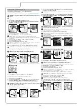
If the side brush does not channel the dirt efficiently towards the centre of the machine, you must adjust
its height in relation to the ground, as follows:
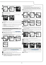
1. Sit on the driver’s seat.
2. Insert the key (1) into the main switch on the control panel. Bring the main switch to its "I" position
by turning the key (1) a quarter turn clockwise (
Fig.1
).
N.B.
: As soon as the machine turns on, the control board will perform a diagnostics procedure,
during which the red LED indicator (2) on the control panel (
Fig.2
) will remain on.
N.B.
: If the control board's diagnostics procedure returns a positive outcome, the red LED
indicator (2) on the control panel (
Fig.2
) will turn off, and an acoustic signal will sound indicating
that the work operations may be initiated.
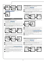
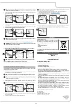
3. Press the side brush head activation - deactivation button (3), on the left side of the steering
column (
Fig.3
).
N.B.
: When the lateral brush is in function, the LED indicator light inside the button (3) will be on.
4. Lower the brush head body by turning the brush head control lever (4) on the rear part of the
steering column (
Fig.4
).
5. Press the drive pedal (5) to begin moving the machine (
Fig. 5
).
3
3
2
1
1
2
ON
N.B.
: Only after the drive pedal has been pressed does the central brush head body and side
brush begin to descend to the working position.
6. As soon as the central brush head is in the working position, carry out the procedures for
securing the machine (see the section "
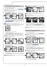
7. Go to the right side of the machine.
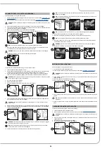
8. Using the right equipment, not supplied with the machine, loosen the counter nut (6) (
Fig.6
).
9. Using the right equipment, not supplied with the machine, loosen the adjusting screw (7) (
Fig.7
),
until the bristles of the brush are squashed on the ground by about two centimetres.
10.
Once the adjustment is finished, tighten the counter nut (6) and move on to the left side brush.
5
5
4
4
6
6
7
7
DISPOSAL
To dispose of the machine, take it to a demolition centre or an
authorised collection centre.
Before scrapping the machine, it is necessary to remove
and separate out the following materials, then send them
to the appropriate collection centres in accordance with the
environmental hygiene regulations currently in force:
• Brushes
• Felt
• Electric and electronic parts*
• Batteries
• Plastic parts (tanks and handlebars)
• Metal parts (levers and frame)
(*) In particular, contact your distributor when scrapping electric
and electronic parts.
EC DECLARATION OF CONFORMITY
The undersigned manufacturer:
FIMAP S.p.A.
Via Invalidi del Lavoro, 1
37059 Santa Maria di Zevio (VR)
declares under its sole responsibility that the products
FLOOR SCRUBBING MACHINES
mod. Magna Basic - Magna 1SL Basic
Magna BS Basic - Magna BS 2SL Basic
comply with the provisions of Directives:
• 2006/42/EC: Machinery Directive.
• 2014/35/EC: Low Voltage Directive.
• 2014/30/EC: Electromagnetic compatibility directive.
They also comply with the following standards:
• EN 60335-1: Household and similar electrical appliances - Safety. Part 1: Generic standards.
•
EN 60335-2-72: Household and similar electrical appliances. Part 2: Specific standards for
automatic machines for floor treatment for commercial and industrial use.
• EN 60335-2-29: Household and similar electrical appliances. Part 2: Special standards for battery
chargers.
• EN 12100-1: Safety of Machinery - Basic concepts, general principles for design - Part 1: Basic
terminology and methodology.
• EN 12100-2: Safety of Machinery - Basic concepts, general principles for design - Part 2: Technical
principles.
• EN 61000-6-2: Electromagnetic compatibility (EMC) - Part 6-2: Generic standards – Immunity for
industrial environments.
• EN 61000-6-3: Electromagnetic compatibility (EMC) - Part 6-3: Generic standards — Standard
emission for residential, commercial and light-industrial environments.
• EN 61000-3-2: Electromagnetic compatibility (EMC) - Part 3-2: Limits – Limits for harmonic current
emissions (Equipment with input current ≤ 16 A per phase).
• EN 61000-3-3: Electromagnetic compatibility (EMC) - Part 3-3: Limits – Restriction of voltage
variations and flicker in low voltage power supply systems for devices with a rated current ≤ 16 A.
• EN 55014-1: Electromagnetic compatibility - Regulations for household appliances, electrical
devices and similar equipment. Part 1: Emission - Regulation for product family.
• EN 55014-2: Electromagnetic compatibility - Regulations for household appliances, electrical
devices and similar equipment. Part 2: Immunity - Regulation for product family.
•
EN 62233: Household and similar electrical appliances - Electromagnetic fields - Methods for
evaluation and measurement.
The person authorized to compile the technical file:
Mr. Giancarlo Ruffo
Via Invalidi del Lavoro, 1
37059 Santa Maria di Zevio (VR) - ITALY
Santa Maria di Zevio (VR), 11/07/2016
Fimap S.p.A.
Legal representative
Giancarlo Ruffo
33

