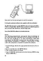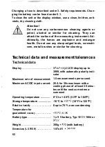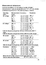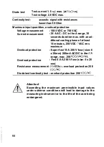
surement input automatically to the AC voltage present, i.e. the
required measurement range is selected automatically.
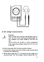
3. Connect the test probes to the test object (load, circuit, etc.).
4. The respective polarity of the measured value is shown in the
display, together with the present measured value.
The AC voltage range
offers, as does the DC voltage range, an
input resistance of
IO
in parallel with 20
(AC-coupled).
Notes!
Due to the fact that the measurement input is very sensitive, it
may be that certain measured values (“phantom measured va-
lues”) are displayed even with test leads unconnected (not
connected to a circuit). This “manifestation” is normal and dis-
appears as soon as a measurement is performed.
,
C DC current measurement
To measure DC current, proceed as follows:
1. Connect the black test lead to the COM socket and the red test.
lead to the
socket if currents up to max. 400
are to be
measured, or with the 20 A socket if currents between 400
and 20 A max. are to be measured..
2. Position the rotary switch to current measurement (4mA or
or
A).
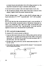
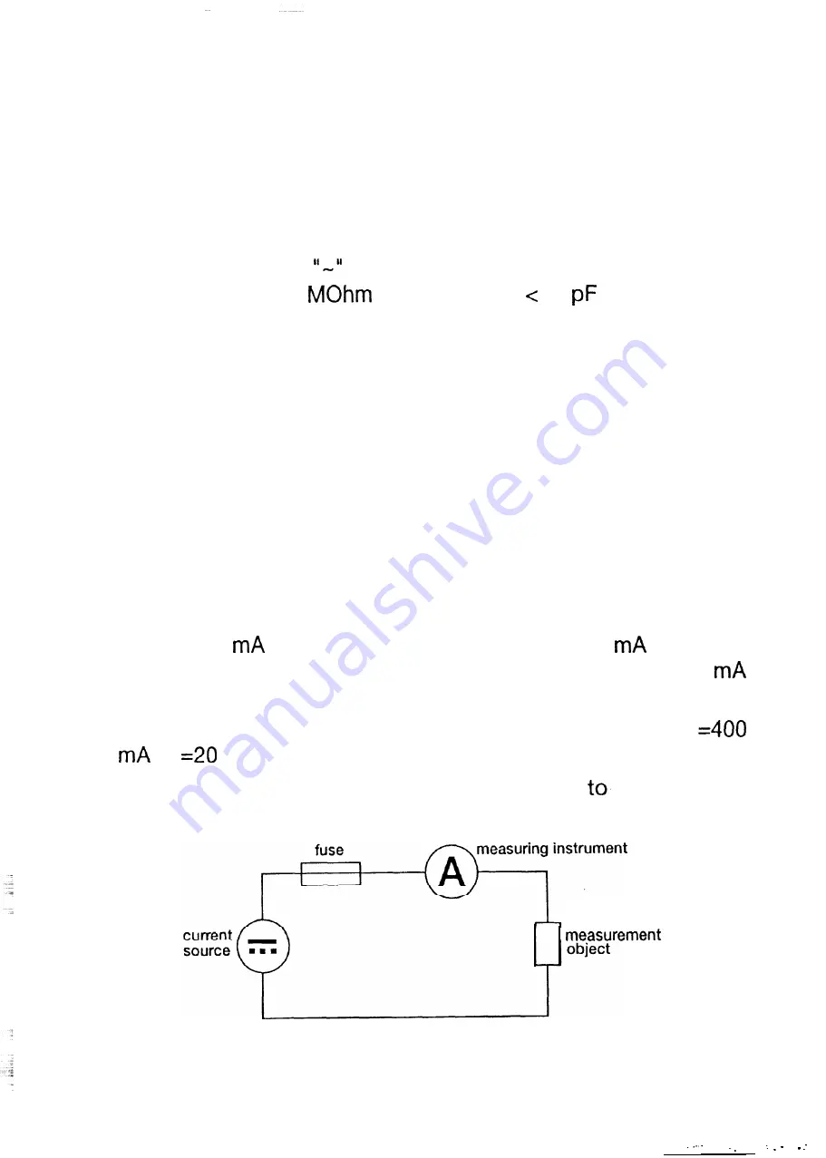
3. Connect the test leads in series with the object
be measured
(see following illustration).
52

