background image

From the library of: Superior Sewing Machine & Supply LLC

Summary of Contents for 223R-2

Page 1: ...ING MACHINE CORP I INDUSTRIAL SEWING CUTTING EQUIPMENT CONSOLIDATED SEWING MACHINE CORP I INDUSTRIAL SEWING CUTTING EQUIPMENT 400 VETERANS BLVD CARLSTADT NJ 07072 From the library of Superior Sewing Machine Supply LLC ...

Page 2: ...From the library of Superior Sewing Machine Supply LLC ...

Page 3: ...ll parts designs are subject to revison and parties to agreements wouldn t be moticed 2 Non Professional wouldn t adjust and maintain the machine except adjustiong the stitch From the library of Superior Sewing Machine Supply LLC ...

Page 4: ...dle the thread and the material 5 14 Threading the needle thread 5 15 Adjusting the tension of bobbin thread and needle thread 5 1 Adjusting the tension ofbobbin thread 5 2 Adjusting the tension of needle thread 6 16 Winding the bobbin thread and adjustment 6 17 Stitch length and forward and backward feeding 7 18 Adjusting presser foot pressure 7 19 The function of the safety clutch and its using ...

Page 5: ...en the machine stand and the floor for further reducing the running noise 2 Install the arm bed and oil reservoir Fig 1 At first the four screw holes of the arm bed should align the four holes of the table and should be plunged through four bolts and tighten the nut Then put the oil reservoir on the arm bed smoothly 3 Install the machine head Fig 2 At frist half of the hings should be made to enga...

Page 6: ...bsered from oppo site side of the balance wheel The motor rotates in the same direction The rotation can be reversed by reversing the plug ofthe motor 4 Adjust the tension of V belt F by moving vertically The proper tension ofV belt is a slack of 10 12mm when the belt is depressed by forefinger 6 Installing the presser foot lift control plate Fig 5 At first the hook A should be connected to the ch...

Page 7: ...umed backward then tighten wood screw C 9 Preparation 1 Cleaning the machine Before the head is packed all the parts of the machine are coated with preventive grease meanwhile the hard ened grease and converged dust on the machine surface during long storage and shipment must be removed by clean cloth with gasoline 2 Examination The parts of the machine may by loose and deformed after long distanc...

Page 8: ...peration for quite long time Please lift the presser foot and run the machine at low speed of 1000 1500 s p m for 30 minutes then increase the speed gradually 12 Installing the needle Fig 9 Tum the balance wheel to lift the needle bar to its hig hest position loosen the needle set screw 1 make the ne edle groove tum to the left side of the operator fully insert the needle shank to the bottom ofnee...

Page 9: ...ide 1 Needle bar thread guide J Needle K When drawing the bobbin thread hold the tip lf the ne edle thread by hand tum the balance wheel to lower the needle bar then lift it to its highest position Pull the ne edle thread and the bobbin thread is drawn up Put the tips of the needle thread and bobbin thread toward front under the presser foot 15 Adjusting the tension of bobbin thread and needle thr...

Page 10: ...ing range CD loosen the presser foot lever loosen the screw A Turn the thread take up spring position disc B counter clockwise to increase the swing range contrary the swing range decrease Tighten the screw A 6 16 Winding the bobbin thread and adjustment Fig 13 The bobbin thread should be neat and tight If the thread is weak please enlarge the pressure of the big thread tension disc A If the threa...

Page 11: ...clutch is preventing the hook and synchronous belt from destroys when the needle or thread is drawn into the hook for abnormal load during the operation When the eccentric pin arrow is aligned with the lower shaft center the load on the safety clutch is small in crease the load when the arrow turns outside Reset the safety clutch the method is Press the button B by left hand and turn the balance w...

Page 12: ...rary decrease the pres ser foot lift volume Then tighten the screw after adjus tment Tum the upper shaft to check ifthere is any col lision Begin to use when every thing goes well 21 Adjusting the feed dog height position Fig 18 Adjust the feed dog height according to the material The feed dog height is 1 2mm for sewing leather or other heavy material 0 8mm for sewing thin material 1 5mm for sewin...

Page 13: ...ight hand divide two screw of the feed cam equally as the oil hold is bisector 23 Adjusting the timing of needle and hook Fig 20 The positon between hook and needle could be set as following order Lift the needle up to 2 5mm from its lowest position The tip ofhook should be straight to the needle center there is about 1 6mm distance between the tip of hook and upside of needle hole If the position...

Page 14: ...5 Installing the hook Fig 22 Replace the hook when the hook is damaged CD Turn the balance wheel to make the needle bar move to its highest position then take down the needle Take down the sliding plate needle plate front and rear presser cover bobbin Loosen the regulating screw A take down the thread separate bracket B Loosen the screw C take down the cover D Slowly move the hook head and take it...

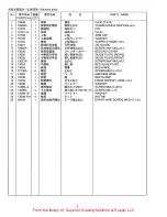
Page 15: ...1 Presser foot mechanism 4 JL Z1 9 10 J i25 J 1 Upper feed mechanism ll lilil t 11 12 i25 J 111 1 Feed shaft mechanism l 111Ji JE 13 14 l lil f FT 1 Lower shaft and rotary hook mechanism t 15 16 iro r 1 Thread tension tl 17 18 1 7 1 Feed reversing lever If t il t 19 20 1 1 1 Accessories 93 14 21 22 lj Parts available at extra charge From the library of Superior Sewing Machine Supply LLC ...

Page 16: ...tll f EJHll 5f I 1 I Machine body 1 14 11 13 OD 10 17 I I I j i E 1 1 1t l 23 r I I 24 15 18 19 From the library of Superior Sewing Machine Supply LLC ...

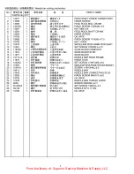
Page 17: ...PLATE REAR 12 13025 1 tf l Ht ti M L J J ti GUIDE PLATE FRONT 13 13027A 4 llj lt bl SCREW 9 64 X40L 6 0 14 13024 1 lfl Ht L BED SLIDE PLATE 15 13004 1 tsEm mll i BED HINGE 16 37100A 6 llj lt bl SCREW M6X1 L 1 0 0 17 13383 1 A MACHING BASE 18 13006 1 ill ti1f m BED CLAMP 19 19403 1 tll ti1f ll t J lt bl HINGE SCREW 1 4X28 L 5 4 20 13008 1 mil 7 t Y F WASHER 21 13388 A 1 mll1f llj mll7f JL rM6X1 SCR...

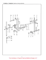
Page 18: ...Hff il IJ 7 1 I lt il IJ fft I Needle bar rocking mechanism 29 17 18 16 22 21 26 44 27 25 r 28 l 0 3 7 10 6 12 11 2 From the library of Superior Sewing Machine Supply LLC ...

Page 19: ... 31 Jl SLIDE BLOCK COMPLETE 14 11876 1 _t jjffi iJ ti i t J 1 Qt SLIDE BLOCK STUD 15 11877 1 _t jjffiff t 1 31 SLIDE BLOCK 16 151 10 A 1 itiff ffit NEEDLEBARROCKFRAME 17 11875 1 ltff ti i ffit f l HINGE STUD 18 10525A 1 itff i iJ ti i ffit f l ll td t SET SCREW 17164 X32L 9 0 19 10560 1 WJ f 4 Ji NEEDLE BAR ROCK FRAME POSITION BRACKET 20 10561A 1 l ii WJ fiffl l l 4 Jvll td t SCREW 11164 X40L 6 5 ...

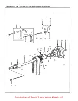
Page 20: ... ttuilt l ffruHt I ttuil 3Cff fflt I Arm shaft and thread take up mechanism 9 10 11 6 1 5 7 15 14 13 12 8 35 33 36 16 17 5 From the library of Superior Sewing Machine Supply LLC ...

Page 21: ...ICK 18 13557 1 t dl t 111 ARM SHAFT 19 10563 1 t flll ll ll Hm eiJJH1Y7 ty 1 WASHER 20 10562 1 t flllifli flll Hill CIJJHiitr ARM SHAFT BUSHING FRONT 21 13361 1 t dl flll ll Urll 7 J t J7 BALL BEARING ADAPTER SLEEVE 22 23637 2 Hlll 7 J 7 t J7 lttll SET SCREW 114X28 L 7 5 23 13074 1 dl 1 Urll 7Jv 7 7 A BALL BEARING ADAPTER 24 10571A 1 Iliff Ffj Ill t 7 1J 7 Alttll SCREW 17164 X32L 20 0 25 10568 1 7...

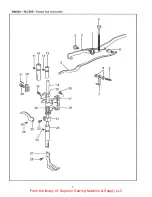
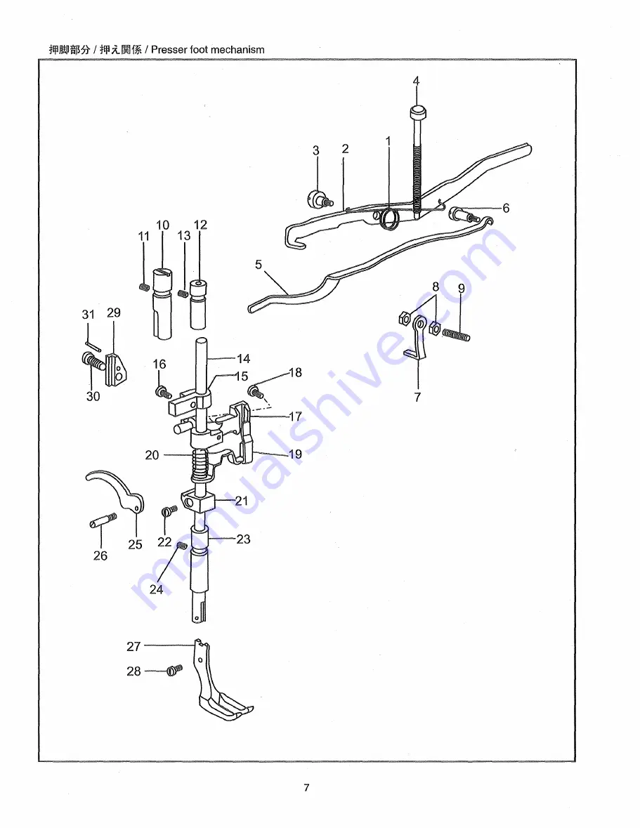
Page 22: ...tllllmlilJHt I illlx 1 I Presser foot mechanism 26 25 27 1 28 4 7 From the library of Superior Sewing Machine Supply LLC ...

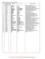
Page 23: ...ER BAR 15 10541 1 tfJ l ff ti tf lx I J PRESSER BAR POSITION GUIDE BRACKET 16 10662A 1 Ill itlSI nt PINCH SCREW 9164 X40L 7 0 17 18479 1 tfJ l ff tfJ lJt t PRESSER BAR LIFTING BftACKET 18 19518 1 Ill itlSI t J t PINCH SCREW 11164X40 L 14 0 19 10546 A 1 tf l ff l f tfJ l t l TENSION RELEASE SLIDE 20 10547 1 tfJ l ff 5 tf lx m l ffi f t J TENSION RELEASE SLIDE SPRING 21 13360 1 tfJ l ff tE tf l m J ...

Page 24: ...il li M1il I Lit IU11 I Upper feed mechanism 9 4 1 V 25 7 10 29 I 1 9 _ _ _ l 1 26 9 From the library of Superior Sewing Machine Supply LLC ...

Page 25: ...LIFTING BELL GRAND 16 10557 1 1fl1f iff k i1i J Jlms LIFTING BELL CRANK LINK 17 10556 1 1fl iffJj gs J Jlms J VIBRATING PRESSER BAR CONNECTING LINK 18 184130 1 filim ft JE J HII li bl LIFTING BELL CRANK CAP SCREW 11 64X40 L B O 19 10728 2 jlifitS fb OIL WICK 20 15117 1 In lit tJI tL li SLIDE BLOCK PLATE 21 8100 2 IDJl U ffl Ill 1Jl tL li li b l SCREW 9 64X40 L 6 5 22 15118 1 In ll 1Jl tL li 3i VIB...

Page 26: ...23 22 24 27 20 18 wo L 19 I I 25 lf i 17 r 0 I 26 0 I 9 6 10 I I I I 12 I _ 11 J 1314 15 From the library of Superior Sewing Machine Supply LLC ...

Page 27: ... I Jf t OILING FELT 12 10532A 1 Ill Ltill PINCH SCREW M4X0 7L 8 5 13 13340 1 C iZS t1 tJA FEED LIFTING CAM 14 13031A 1 fli lll fli ii 5 1Sbill POSITION SCREW MSX0 8L 4 7 15 13085A 1 Ill Ltill SET SCREW MSX0 8L 4 3 16 13473C 1 iZS ffi 4 mftf iZS J 4 Jl FEED BASE COMPLETE 17 13472A 1 Ill iZS J A t 1 lt ill SCREW M2 5X0 45 L 6 5 18 13475 1 iZS fiJ Ji frl iJ ti 4 iZS J f kH HINGE PIN 19 0148 H 1 im 7 ...

Page 28: ...haft and rotary hook mechanism 33 r 39 liif lr 41 34 40 37 45 44 43 48 46 47 Or 51 5o _ 49 1 31 11 l1 12 10 j 9 f 8 6 ftr 7 17 19 13 _ 1 I I I I 25 26 27 G s 21 22 y 30 28 _ 29 From the library of Superior Sewing Machine Supply LLC ...

Page 29: ...SCREW 114X32 L 10 5 25 10615 1 l M it l Jv r7 IJ t t n SAFETY CLUTCH LOCKING LEVER SPRING 26 10614 1 ti11 t t HINGE PIN 27 10619 1 1 5 l Jv r IJ 7 7 IJ IJ THROW IN LATCH SPRING 28 10617 1 l tJj i l J r 1 Jj JI SAFETY CLUTCH RATCHET 29 10618 1 1 tI J ll fi i 1 r7 1 J_ J il iMI RATCHET CONNECTION LINK 30 10620 1 l t7fCJ i11 l Jv r7 IJ tl J THROW IN LATCH PIN 31 13054 1 i oJ PJtliMtmJE f U 4 Y i7 v r...

Page 30: ... ff Ht I ifaJ T 1 I Thread tension 20 27 28 J e i l 7 n 8 1 9 11 12 13 15 16 From the library of Superior Sewing Machine Supply LLC ...

Page 31: ...1 mJ t 11 lUJ TENSION RELEASE WASHER 14 19533 1 Wa1 5 A fiJ 7 1 4 TENSION SPRING D 1 4 15 28206 1 mJ t c v y t At yr NUT WASHER 16 19513A 1 1 1 3 c v 1 7 1 TENSION THUMB NUT 7132X40 17 10678 1 11 lSf TENSION RELEASE PLATE 18 19422 2 t tili r 11 lSt f 1 HINGE SCREW 9164X40 19 18085 1 l j J tb t SCREW 11164X40 L 8 5 20 10720 1 t tili T 11 lSI I TENSION RELEASE LEVER ROD 21 19512 1 5 jfiff 5I A7 J 7 ...

Page 32: ... n r I Feed nt k I 71 l li Z reversing lever _ _ I 6 8 w 26 1 25 24 I I _ 1 4 17 From the library of Superior Sewing Machine Supply LLC ...

Page 33: ... MIDDLE 11 19415 1 I Jff J tnt SCREW 1 4X28 L 20 0 12 4113 1 l J 1 Jl T NUT 1 4X28 13 10571A 1 I Jff J t fd t SET SCREW 17 64 X32L 20 0 14 10725 1 Bl fQ 7 r Jv r OIL FELT 15 13415 1 f Wifflaili I Jff Lr 1 nt FEED REGULATING LEVER 16 13418 1 miFo J iH J tilt STITCH LENGTH PLATE 17 7041A 4 l Jff Jl fd t SCREW 1 8X40L 7 0 18 13417 1 miFo J P fpr 170 FEED ADJUSTING PIPE 19 13416 1 tt l J 1 c v y r KNU...

Page 34: ...5 4 11 I 3 2 1 8 15 16 9 19 From the library of Superior Sewing Machine Supply LLC ...

Page 35: ... v 7 DOUBLE HEAD WRENCH 7 10656 6 L f t BOBBIN 8 8123 1 Jtim im OIL WITH OILIER 9 10734 1 ffif f t r BOBBIN WINDER COMPLETE 10 13098 1 m iJl llt ffif f 9 Jv t r PEDAL COMPLETE 11 13079 1 I J CHAIN 1 00 M M 12 N0122 3 nDPX17 22 ffit DPX17 22 MEEDLE DP X 17 22 13 11487 1 pg 1FJt v 7 3 1 HEXAGON WRENCH 3MM 14 11969 1 1 1 mt F 3mm v 7 2 5 1 HEXAGON WRENCH 2 5MM 15 13089 1 m 2 5mm im OIL PAN 16 35254 1...

Page 36: ... 1 1 I llj I Parts available at extra charge mm i I Jv r jJ f l Belt cover 12 11 8 8 9 1 f flj J j fl I 7 1 tJ tJ 1 f I Finger guard 21 18 19 From the library of Superior Sewing Machine Supply LLC ...

Page 37: ...i l J f Jt JJ Frmllhii F 17 11830 1 Ill ttnt 18 10677 1 m 7 y 7 19 15081 4 Ill t lt 20 16287 4 m 7 y 7 E tm1Iti f I 7 1 tJ jJ F 1 I Finger guard No f 5 P 1 f f j 1 1 QJ I PARTS No QTY 21 10937 1 E tm 1it 71 7 J 7i F 22 10677 1 m 7 Y 7 23 10749A 1 ti I1ID jE IJI 9 f tlt 71 ii ti r ffl 22 PARTS NAME BELT GUARD COMPLETE BELT GUADRD TOP COVER BELT GUARD SET PLATE BELT GUARD BODY SCREW 118X44 L 4 0 SCR...

Page 38: ...cos w CONSOLIDATED SEWING MACHINE CORP CONSEW INT L LTD N Y N Y U S A TOKYO JAPAN WWW CONSEW COM From the library of Superior Sewing Machine Supply LLC ...

Reviews: