background image

Summary of Contents for 277RFS-3

Page 1: ...OP RAT ON INSTRUCT ON PARTS l ST FOR ...

Page 2: ...edle thread 5 15 Adjusting the tension of bobbin thread and needle thread 5 is Winding the bobbin thread and adjustment 6 17 Stitch length forward and backward feed 0 7 is Adjusting presser foot pressure 19 Adjusting the amount of presser foot lift 20 Adjusting the timing of feed 8 21 Adjusting the timing between needle and hook 8 22 lnstalling the hook positioning bracket and hoolc 8 i Machine bo...

Page 3: ...o E 10 I STRUCTIO ...

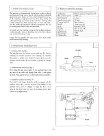
Page 4: ...flat floor for ensuring its smooth operation and reducing its vibration Meanwhile a rubber mat should be inserted between the machine stand and the floor for further reducing the running nOIse 2 Install the base and oil pan Fig 1 First Align the four screw holes of the machine base with the ones of the table and plunge four bolts A and tighten the nuts Then put the oil pan on the machine base smoo...

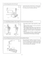
Page 5: ... rotate counter clockwise observed from opposite side of the balance wheel The motor D rotates in the same direction Thf rotation of motor can change by reversing the plug of the motor 4 Adjust the tension of V belt by moving motor upward or downward The projJer tension of V belt is a slack of 1O 12mm when the V belt is depressed by forefinger 6Jnsttamng the presser foot mt contro piatte lFig 5 c ...

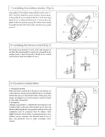
Page 6: ... with the thread stand then tighten the nut C 1 Clearing the machine Before the head is packed all of the parts of the machine are coated with anti rustgrease meanwhile the grease can harden and the dust can cover the machine surface during long time storage and shipment so the dust and grease must be cleared by clean cloth with gasoline 2 Examination Although every machine is conformed by strict ...

Page 7: ...ing quite long time Please lift the presser foot and run the machine at a low speed of 1000 1500 s p m for 30 minutes then increase the speed gradually 9 Jnstamng the needie Fig 9 4 Tum the balance wheel to lift the needle bar to its highest position loosen the needle sei screw and make the needle groove to the left side of the operator then fully insert the needle shank until to the bottom of the...

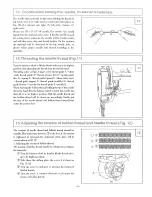
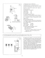
Page 8: ... take up G lihread guide upper F cj h read guide middle H l thread guide Qower K l needle bar thread guide J l needle K When drawing the bobbin thread holding the tip of the needle thread by hand thru the balance wheel to lower the needle bar then lift it to ias highest position Pull the needle thread and the bobbin thread will be drav Tfi up accordingly finally put the tipe of the needle thread a...

Page 9: ...over 8mm about8mm Heavy materials less 8mm The method of adjusting swing range as Fig 4 j Loosen the presser foot lifter 2 Loosen the screw A Tum the disc B counter clockwise to increase the swing range contrary the swing range decrease j Tighten the screw A i rELWinding the bobbin thread and adjustment Fig 13 13 A D E The bobbin thread should be neat and tight If the thread is weak please increas...

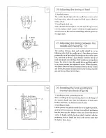
Page 10: ...ou sew heavy materials Adjust the screw as Fig 15 first loose the nut A then tum the SCl ew B clockwise to increase the pressure contrary decrease the pressure After the proper pressure is got tighten the screw A Turn the screw C the pressure can be lightly adjusted Counter clockwise Clockwise P 19 Adjusting the amount of presser foot iiH Fig 1S The method of adjusting the amount of presser foot M...

Page 11: ...side of needle hole If the position is wrong please loosen the screw A move the needle bar up and down until it is on proper position then tighten the screw When adjustmet also please notice the lateral clearance between the tip of hook and needle the proper clearance between the bottom of needle gap and the tip of hook is O O Smm 22Jnstalling the hook positioning bracket and hook Fig iS 1 Install...

Page 12: ...P T ...

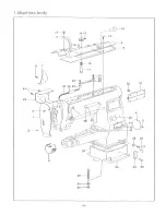
Page 13: ...44 43 2 33 l 1 34 J 35 3 9 ...

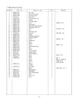
Page 14: ...7 Lubrication dial stud 1 18 49WF2 014 Oil gauge window 1 19 49WF2 012 Screw 7 SM9 64 x40 20 49WF2 0l5 Spring plate 1 21 49WF2 012 Screw 1 22 7KTI 020 Washer 1 23 16WF3 014 Screw 1 SM1 8 x 40 24 49WF2 016 Oil adjusting collar 1 25 49WF2 003 Base 1 26 49WF2 OlO Oil pan 1 27 22WF2 006 Screw assembly 1 28 37T4 411 Spring washer 1 29 37T4 409 Connecting hook 1 30 22WF2 020 Screw 1 SM1I4 x 28 31 37T4 4...

Page 15: ...2 3 1 4 l s LPf 6 20 18 19 I I I 16 17 7 o 8 1 1 I 1 9 10 11 12 24 11 27 28 I hS I I I I I I I I I I I I I I I I I I I I I W 37 38 I I 32 34 35 36 ...

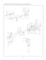
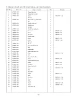
Page 16: ...I 021 Washer 1 19 22WFI 053 Upper shaft bush L 1 20 I 16WFI 025 Felt 2 21 49WFI 007 Upper shaft 1 22 49WFl 108 Upper shaft bush M 1 23 16WFI 004 Screw 1 SM17 64 x 32 24 16WFI 025 Felt 1 25 49WFI 012 Upper shaft collar 1 26 22WFl 048 Screw 2 SM1I4 x 28 27 49WFI 013 Upper shaft bevel gear 1 28 49WFI 014 Screw 1 SM1I4 x40 29 49WFl 015 Set screw 1 SM1I4 x40 30 49WFI 009 Upper shaft bush 1 31 16WFI 004...

Page 17: ...73 I I 1 L46 II 1 I U 771 l I g 50 I I 15 57 0 59 t 66 68 9 65U 64 I 28 27 U w Z lro 13 J 12 I I if ilro P i 5 14 0 I o n f Ii U II OF 8 I 3B iO 10 9 1 2 I 1 1 7 I 0 0 42 l 43 45 82 I 3 if o o r 13 I I o I 3 I i iii t ...

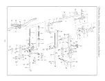
Page 18: ...ink 1 61 16w F3 025 Setscrew 1 SM17I64 x 32 20 22WF5 026 Swing plate 1 62 49w F3 007 Presser bar bush 1 I 21 49WFS 009 Pressure adjustment screw 1 SM5 16 x 24 63 22w F3 014 Set screw 1 SM9 64 x40 22 22w FS 031 Spring rod 1 64 49WF3 015 Outer presser foot 1 23 49WFS 007 Spring 1 65 6K2 042 Screw 1 M6x 1 24 22WF5 028 Link 1 66 49VtTF3 D08 Presser bar guide shaft 1 2S 22WF5 009 Slide block 1 67 22WF3...

Page 19: ...3 6 1 7 14 1 I I I _________ L I _________ I _ r 21 v 20 22 ...

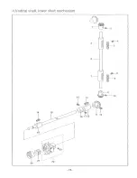
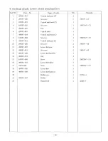
Page 20: ...1 8 16WFI 004 Set screw 1 SM17 64 x 32 9 49WFI 021 Vertical shaft gear L 1 10 49WFI 020 Set screw 2 S1 1114 x 40 11 49WFl 027 Lower shaft gear 1 12 49WFI 015 Set screw 2 SM1I4 x 40 13 49WFl 030 Lower shaft bush B 1 14 49WFI 031 Felt 1 15 16WFI 004 Screw 1 SM17 64 x 32 16 49WFl 032 Lower shaft collar 1 17 7K13 026 Screw 2 SlVHl 64 x 32 18 49WFI 026 Lower shaft 1 19 49WFI 029 Lower shaft bush A 1 20...

Page 21: ...I I 66 73 L J 4 I V 1 5 6 I J JJ 9___ 7 r 10 t _ 67 13 14 11 12 65 60 41 64 6 I 62 59 52 51 0 49 50 48 2 29 I 23 __ 24 31 32 I I 44 43 34 35 136 Lnb l 37 4039 i 38 01 ...

Page 22: ... shaft 1 53 49WF4 023 Link shaft 1 17 49WFI 006 Ruhberplug 1 54 Oil wick 1 18 Oil wide I 55 49WF4 022 Feed shaft crank A 1 19 49WF4 008 Reverse stitching control rod 1 56 49VfF2 028 Feed arm bracket 1 20 2lWF3 OlO Screw 1 SlVI3 16 x 32 57 22WF4 014 Screw 2 SMll 64 x 40 21 61 2 019 Screw 2 lVI4 x 0 7 58 49WF4 028 Pin screw 1 22 22TI 007 Washer 2 59 49WF4 027 Feed arm 1 23 49WF4 006 Stitch length re...

Page 23: ... echan s_m_l_ _____ Co Threading m 71 u 1 ___ QV I I fT I jill i jl I I J III 2 _ g 19 21 ...

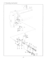
Page 24: ...plate 1 12 16WF2 046A15 Screw 2 SM9 64 X 40 13 16WF2 047 Thread release shaft 1 14 16WF2 049 Spring stopper 1 15 16WF2 050 Screw 1 SM9 64 x 40 16 16WF2 046Al Upper thread tension board 1 17 16WF2 046A12 Pin 1 18 16WF2 046A13 Tension release pin 1 19 16WF2 046A6 Thread tension disc 2 20 16WF2 046A5 Tension reiease disc 21 16WF2 046A4 Thread tension spring 1 22 153029 Stopper disc 1 23 16WF2 046A3 T...

Page 25: ...70 Accessories 8 1 3 11 15 18 19 13 22 26 9 I I I T rf 23 27 28 21 ...

Page 26: ...belt 1 otype 1380mm 12 49WFl 033 Bobbin 4 13 Wrench 1 11 12 14 18WFl 013 Pedal assembly 1 15 lSWFI 017 Chain 1 1000mm 16 18WFI 016 Chain hook 2 17 33TF 014 ScrEw driver L 1 18 33TF 013 Screw driver M 1 19 33TF 012 Screw driver B 1 20 Wrench 1 8 x 10 21 Machine cover 1 22 lWF5 032 Screw 8 SMlll64 x 40 23 49WF6 003 Support screw 2 2 24 49WF6 002 Support screw 1 1 25 22WF6 015 Belt cover 1 1 26 22WF6...

Reviews: