OPERATING & INSTALLATION INSTRUCTION 2-POST-LIFT
Installation and Commissioning of Chain Lift H264/H265/H325
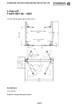
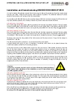
Set up the base frame (special accessory) in the desired location. Anchor it to the floor using safety plugs.
Torque of the M12 safety plugs according to the instructions of the manufacturer. The anchor bolts must
locate securely in the concrete according to the manufacturer’s instructions.
The base frame must lie completely flat. When installing the base frame, the M16 x 45 screws inserted in the
frame must be used! (The M16 x 40 screws contained in the standard accessory kit must not be used).
In accordance with EN1493 there must be a safety margin of 500 mm minimum between the lift columns and
any other obstacle (wall, etc) and, similarly, between any load to be raised and another obstacle.
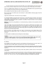
After setting up the columns bring the lifting carriage (untensioned lift) to the same height. Insert plugs for the
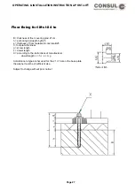
base plates (the base plates must lie quite flat!).It is necessary to use 10 heavy duty M16 anchor bolts (eg,
Hilti HSL -G -TZ, or sumilar anchors from another manufacturer).
After setting up the columns bring the lifting carriages on unternsioned lifts to the same height and pull the
chain up. When doing this ensure that the glide unit of the chain break switch lies cleanly on the chain and
that the activating pin does not yet touch the limit switch.
Only when the chain breaks can the limit switch tappet be pressed upward so that the drive is switched off. If
necessary the limit switch may need readjusting (by moving it vertically).
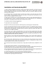
Position the chain guide approximately 1,3 m from the base plate. Then install the chain cover so that the
hole in the sheet metal lies above the M6 thread of the chain guide. The base plate (with the columns) is
raised until the chain is under slight tension. After repeatedly checking the installation site, insert the plugs
for the base plates (the base plate must be completely flat!
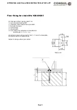
To bolt down the base plates, 10 M16 heavy duty anchors are necessary ( eg. Hilti HSL - G - TZ,
or similar anchors from another manufacturer).
The drilling depth in the concrete (BN25) must (eg, Hilti HSL G-TZ) be to a minimum depth of 125 mm. The
depth of the anchor bolt must be no less than 100 mm. The plugs must have a minimum resistance strength
of 9 kN.
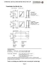
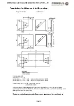
The torque value is 120 Nm. The length of the plugs to be used should be according to the information in the
section “Foundations”. The above mentioned plug information relates to Hiliti Heavy Duty Anchors HSL - G -
TZ M16. Other makes of plug may be used as long as they are a permitted design for the concrete. Plugs
not included.
The lift columns should be vertical. On no account should they lean inward.
A slight outward lean (up to 10 mm ) is desirable. If necessary extra shims can be placed between the
column base plates and the floor for leveling purposes.
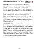
First screw the main column to its base plate ( torque 200 Nm ) then push the (lightly screwed down) slave
column outwards in order to connect the chain. For this use the enclosed chain adjustment plate. Stick the
narrower side through the near side of the distance plate (long hole downward) and turn it through 90
degrees. By a short pull on the plate check that it does not slip out. Finally stick a larger screwdriver (or
something similar through the hole. The lower end of the screwdriver should lever itself againgst the firm
base plate! Now the chain can be tensioned by pulling back the screw driver (or an assembly tool which can
lever itself against the enclosed chain plate can also be used for the purpose).
The chain has the correct tension when it can be pressed together in the middle (without chaing guide) using
only hand power. The slave column is likewise screwed to its base plate with a torque of 200 Nm. The chain
guide is screwed to the chain plate using the enclosed 12 M6 screws (with washers).
If the available floor is not even and the chain cover does not lie flat (clattering noise), then the cover must
be secured with 2 screws. For this drill 2 holes through the middle of the sheet metal, diameter 9 mm (each
Page 36
Summary of Contents for 2.25 EMC
Page 67: ...OPERATING INSTALLATION INSTRUCTION 2 POST LIFT Electric diagram H342 Page 67 ...
Page 68: ...OPERATING INSTALLATION INSTRUCTION 2 POST LIFT Electric diagram H325 Page 68 ...
Page 70: ...OPERATING INSTALLATION INSTRUCTION 2 POST LIFT Electric diagram with push button Page 70 ...
Page 71: ...OPERATING INSTALLATION INSTRUCTION 2 POST LIFT Page 71 ...
Page 72: ...OPERATING INSTALLATION INSTRUCTION 2 POST LIFT Page 72 ...
Page 73: ...OPERATING INSTALLATION INSTRUCTION 2 POST LIFT Page 73 ...
Page 74: ...OPERATING INSTALLATION INSTRUCTION 2 POST LIFT Page 74 ...
Page 75: ...OPERATING INSTALLATION INSTRUCTION 2 POST LIFT Page 75 ...
Page 76: ...OPERATING INSTALLATION INSTRUCTION 2 POST LIFT Page 76 ...
Page 77: ...OPERATING INSTALLATION INSTRUCTION 2 POST LIFT Page 77 ...
Page 78: ...OPERATING INSTALLATION INSTRUCTION 2 POST LIFT Page 78 ...
Page 79: ...OPERATING INSTALLATION INSTRUCTION 2 POST LIFT Page 79 ...
Page 80: ...OPERATING INSTALLATION INSTRUCTION 2 POST LIFT Page 80 ...


