background image


The device complies with the safety standards for  medical electrical equipment  or system 

electromagnetic  compatibility  in  IEC60601-1-2.  Electromagnetic  environments  exceeding  the 
IEC60601-1-2 standard may cause harmful interference to the device or prevent the device from 
performing its intended function or degrade its performance. Therefore, if there is a phenomenon 
that  does  not  match  its  function  during  use,  be  sure  to  confirm  and  eliminate  adverse  effects 
before continuing to use it. Corresponding precautions for this situation are given in this manual. 

n


The device or system should not be used near or stacked with other devices. If it must be 
used near or stacked with other devices, it should be observed and verified that the device 
is working normally under the configuration it is using. 

n


The use of ACCESSORIES other than those specified by the MANUFACTURER  of the 
device or system,  may result  in increased EMISSIONS  or decreased IMMUNITY  of the 
ME EQUIPMENT or ME SYSTEM. 

n


Effect from radiated electromagnetic waves: 

        The use of a mobile phone may affect the operation of the device. When installing medical 

electrical equipment, be sure to remind people around the device to turn off mobile phones and 
small radios. 

n


Effect from shock and conduction electromagnetic waves: 

        High  frequency  noise  from  other  equipment  can  enter  the  device  through  the  AC  socket. 

Please identify the source of noise, if possible, stop using the equipment.  If the equipment can 
not  be  deactivated,  use  noise  cancellation  equipment  or  take  other  measures  to  reduce  the 
impact. 

n


Effect from static electricity: 

        Static  electricity  in  a  dry  environment(indoor)  may  affect  the  operation  of  the  device, 

especially  in  winter.  Before  using  the  device,  humidify  the  indoor  air  or  discharge  the  static 
electricity from the cable and operator. 

n


Effect from thunder and lightning: 

        If there is thunder and lightning nearby, it may cause a voltage surge in the device. If you 

are concerned about danger, disconnect the AC power and use the internal power supply. 

2.16 Notes concerning ECG waveform measurement and analysis 
2.16.1 The identification of P wave and Q wave is not always reliable with intensive EMG or AC 

interference. Neither are the ST segment and T wave with baseline drift. 

2.16.2 Winding and unclear end position of S wave and T wave may cause error in measurement. 
2.16.3  When  R  wave  is  uninspected  caused  by  some  leads  off  or  QRS  wave  low  voltage,  the 

heart rate measurement may deviate greatly from the correct. 

2.16.4 In case of QRS low voltage, ECG axis calculation and border-point identify of QRS wave 

are not always reliable. 

2.16.5  Occasionally,  frequent  ventricular  premature  complexes  may  be  identified  as  dominant 

beat. 

2.16.6  Merging  of  versatile  arrhythmia  may  result  in  unreliable  measurement  because  of  the 

difficulty in distinguishing P wave in such situation. 

2.16.7  The  device  has  an  automatic  analysis  function  that  automatically  analyzes  the  obtained 

ECG  waveform  without  reflecting  all  the  patient’s  status.  The  results  of  the  analysis  may 

Summary of Contents for 33221

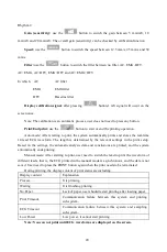
Page 1: ...LTD No 112 Qinhuang West Street Economic Technical Development Zone Qinhuangdao Hebei Province PEOPLE S REPUBLIC OF CHINA Made in China ECG300G 33221 Shanghai International Holding Corp GmbH Europe Ei...

Page 2: ...plied by battery Degree of protection against electric shock type CF defibrillation proof applied part Working mode continuous running equipment Enclosure protection class IPX0 Measurement results sha...

Page 3: ...e physicians by contract The company performs device repair in warranty period a year and maintenance service after warranty period The company responds timely to the user s request The user manual is...

Page 4: ...any s written permission is prohibited All information contained in this user manual is believed to be correct Our company shall not be liable for incidental and consequential damages in connection wi...

Page 5: ...5 Operation Precautions 13 5 1 Precautions before use 13 5 2 Precautions during operating 13 5 3 Precautions after use 13 Chapter 6 Preparations before Operation 14 6 1 Installation of recording paper...

Page 6: ...ter 9 Maintenance 34 9 1 Battery 34 9 2 Recording paper 35 9 3 Maintenance after use 35 9 4 Lead cables and electrodes 36 9 5 Silicone rubber roller 36 9 6 Cleaning of thermal print head 36 9 7 Dispos...

Page 7: ...ards ambulances and carrying out medical consultations It can be used by medical institutions to record human ECG signals collect and extract the ECG waveform 1 3 Main technical specifications 1 3 1 E...

Page 8: ...re and analyze 1 3 16 Manual record record according to manual record format 1 3 17 Measurement parameters HR P R interval P Duration QRS Duration T Duration Q T interval Q Tc P Axis QRS Axis T Axis R...

Page 9: ...auxiliary reference for doctors to make diagnosis The analysis result cannot be used as the only standard for diagnosis A comprehensive evaluation should be made by professional electrocardiogram tec...

Page 10: ...on or fire 2 9 Do not use the device in medical hyperbaric oxygen chamber otherwise there is a danger of explosion or fire 2 10 This device is not intended to act directly on the human heart If this d...

Page 11: ...stop using the equipment If the equipment can not be deactivated use noise cancellation equipment or take other measures to reduce the impact n Effect from static electricity Static electricity in a...

Page 12: ...not comply with the doctor s diagnosis Therefore the final conclusion needs to be comprehensively analyzed by doctors in combination with analysis results patient clinical characterization and other t...

Page 13: ...user manual and operation notes 3 3 2 Faults or injuries caused by dropping accidentally after purchase 3 3 3 Faults or injuries caused by repair reconstruction decomposition etc not by our company 3...

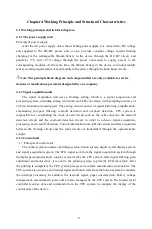
Page 14: ...ss filtering lead off detection and overload detection CPU system is responsible for coordinating the work of each circuit such as the A D converter the lead off detection circuit and the overload det...

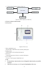
Page 15: ...reen Display patient s ECG and related information 3 Button area Control the operations of the device and enter information 4 Cover switch To open or close the paper compartment cover Note Do not put...

Page 16: ...ed such as archiving managing and analyzing ECG data which facilitates clinical research organization teaching and training as well as program upgrade case import and export and connection with extern...

Page 17: ...te that the battery is being charged 3 MENU Menu button 4 MODE When the device in sampling interface use MODE button to select the print mode 5 1mV Calibration button 6 PRINT Print the sampled ECG wav...

Page 18: ...oof type CF applied part USB interface PAZIENTE Lead cable socket Serial number Manufacturer Date of manufacture Product code Lot number Latex free Temperature limit Atmospheric pressure limit Humidit...

Page 19: ...ing the earth or a hospital bed 5 1 9 Clean the lead cable with neutral solvent Do not use alcohol based cleaners or gemicides 5 1 10 Ensure that the device is running within the normal ambient temper...

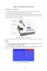
Page 20: ...with grids should be faced downwards and then install it to proper position in the paper cabinet Figure 6 1 Installation of recording paper 2 Close the paper cabinet cover it would be better to leave...

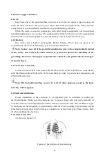
Page 21: ...he reliability of the grounding Do not use other pipes as ground wire otherwise the patient may be in danger of electric shock 6 3 Lead cable connection Connect the lead cable to the lead cable interf...

Page 22: ...e chest electrodes should not touch each other to avoid short circuit 6 4 2 Limb electrodes The limb electrodes should be placed on the soft skin of both hands and feet Before connecting clean the ski...

Page 23: ...ood contact with the skin 6 4 4 Lead method and system As shown in Figure 6 5 Figure 6 5 Lead system 6 4 5 Lead off and overload indication The device can check the connection status of the lead at an...

Page 24: ...ice will automatically enter this interface after powering on to enter the case management interface in this interface user can query modify or delete case information to view the placement of leads t...

Page 25: ...mple End sampling After the device starts sampling use the button to end the sampling and back to the main interface Switch lead When the device does not simultaneously display 12 leads use the and bu...

Page 26: ...veform The length is determined by the relevant settings in the print setup Based on the settings the automatic analysis data and conclusions are printed and the system automatically ends printing Man...

Page 27: ...ON OFF Turn on or off the Baseline filter Rhythm Lead Any lead among the 12 leads Set the rhythm lead that used for printing under rhythm mode Show Style 3 Leads 6Leads 12Leads Set the display method...

Page 28: ...d Click OK to confirm the entry and exit the interface The keyboard may have input restrictions according to the limitation of content The restricted keys will be grayed out and unavailable as shown b...

Page 29: ...Adv opr to enter the following interface Click Query to enter the query interface shown below Input query conditions and click Query to obtain expected results After clicking Clear the system will cl...

Page 30: ...e Make sure the input information is correct click Review to enter the review interface which is similar with the sampling interface In current interface user could adjust the time period of displayed...

Page 31: ...de Auto 4 3 Auto 3 4 Auto 2 6 and other print modes that applicable for current case The system takes the selected option as print mode Rhythm Lead Any lead among the 12 leads Set the rhythm lead that...

Page 32: ...ht 30Seconds 1 Minute 2 Minutes 5 Minutes 10 Minutes Always On If there is no operation after reaching the set time screen backlight will turn off If it is set to Always On the backlight will always k...

Page 33: ...e AC filter EMG Filter ON OFF Turn on or off the EMG filter DFT Filter ON OFF Turn on or off the Baseline filter Info Input Before After None Set to input the case information before or after sampling...

Page 34: ...nd Premature The system will use the input value as a standard of judging premature beat Pause Time The system will use the input value as a standard of judging beat pause Tachycardia The system will...

Page 35: ...aveform Average QRS 2 6 2 6 Mark 3 4 3 4 Mark 4 3 4 3 Mark None When Print Mode is set to Auto or Rhythm the system uses the selected format to print the average QRS waveform Auto Di agnosis All Data...

Page 36: ...e keeps the same with print time 7 12 Lead placement In the main interface click to view the schematic diagram of lead placement the European Standard is shown as below Click any button to exit 7 13 A...

Page 37: ...the metal bed is grounded reliably Whether the patient is touching the wall or metal parts of the bed Whether the patient touches other people Whether there is high power electric equipment working ne...

Page 38: ...aveform 1 Grounding cable is not connected reliably 2 Lead cables are not connected reliably 3 There is AC interference 4 Patient is nervous and can not keep quiet 1 Check the power cord and lead cabl...

Page 39: ...ent movement 1 Charge the battery 2 Keep patient still Unclear waveform 1 Low battery 2 The printer head surface is dirty 3 The thermal paper problem 1 Charge the battery 2 Cut off the power clean the...

Page 40: ...el switches between icon f to icon c 9 1 2 The device can print for 3 hours or work for more than 10 hours in standby mode when battery is completely charged When the device is powered by battery a ba...

Page 41: ...uch recording paper please contact your dealer or the company Please be careful 9 2 1 When using recording paper it is absolutely not allowed to use recording paper with wax on the surface or in grayi...

Page 42: ...cquisition In this case the electrode must be replaced 9 5 Silicone rubber roller The silicone rubber roller should be smooth and free of stains otherwise it will affect the ECG recording effect In or...

Page 43: ...nel who is responsible for maintenance of the device 9 8 3 The device belongs to measuring instrument User should send the device to national designated inspection institution for inspection according...

Page 44: ...tions on the package when opening the package 10 2 2 After unpacking please check the accessories and accompanying documents in accordance with the packing list then start inspecting the device 10 2 3...

Page 45: ...rdiographs Clause 50 Accuracy of operating data the appendix gives a description of verification process and results of the performance for automated measurement and automated interpretation 2 Automat...

Page 46: ...orepart anteroseptal MI 23 Old anteroseptal MI 24 Early anterior MI 25 Possible acute anterior MI 26 Old anterior MI 27 Early extensive anterior MI 28 Possible acute extensive anterior MI 29 Old exten...

Page 47: ...ion is shown as below Application and diagnosis To detect the abnormal of heart of human body examination items refer to above description Population Teenagers and adults age range 12 87 Application s...

Page 48: ...from the previous qrs complex to the current location is less than 150ms then give up the location Otherwise take the 1 4 of threshold value as a reference find the beginning of qrs complex within 10...

Page 49: ...cessing superimpose the absolute value of slope for 12 lead signals 3 Use the preprocessed data to carry on the searching of QRS complex P wave and T wave as the followings 4 Read the next data of qrs...

Page 50: ...ethod of superposition of the slopes for all leads therefore the equipotential segments before and after the QRS complex are partly included in the start and end points of the QRS complex It is depend...

Page 51: ...wave the difference between the max value and the baseline would be the amplitude of T wave 5 Recognition of minimum wave The minimum wave can be recognized by the algorithm according to the requireme...

Page 52: ...voltage sum from the beginning point to the end point of QRS complex on lead III SI voltage sum from the beginning point to the end point of QRS complex on lead I T electric axis SIII voltage sum from...

Page 53: ...II aVF amplitude of P wave 0 25mV and P wave duration 110ms 7 QRS low voltage Voltage of I aVF limb leads 0 5mV and voltage of V1 V6 chest leads 0 8mV 8 Cardiac electric axis normal QRS axis between...

Page 54: ...eroseptal MI Early myocardial infarction change of leads V1 V2 V3 no change of leads V4 V5 22 Possible acute forepart anteroseptal MI Acute myocardial infarction change of leads V1 V2 V3 no change of...

Page 55: ...ion change of leads I aVL no change of leads II III aVF V4 V5 V6 39 Early inferior MI Early myocardial infarction change of leads II III aVF no change of leads I aVL 40 Possible acute inferior MI Acut...

Page 56: ...r myocardial ischemia Severe ST segment depression of leads V1 V2 V3 V4 V5 56 ST depression apical myocardial ischemia Severe ST segment depression of leads V4 V5 and no change of leads V1 V2 V3 57 ST...

Page 57: ...1 MA0125 Automated interpretation CSE diagnostic database D_0001 D_1220 Customized data 000001 000549 4 2 CTS introduction The CTS computerized ECG conformance testing project was launched in 1989 by...

Page 58: ...agnostic items Item Number Normal 382 Left ventricular hypertrophy 183 Right ventricular hypertrophy 55 Biventricular hypertrophy 53 Anterior myocardial infarction 170 Inferior myocardial infarction 2...

Page 59: ...ltage axis Determined by the diagnostic results of ultrasonic examination 5 Conduction block Determined by the physician diagnostic results of cardiac catheterization The standard of normal population...

Page 60: ...00 CAL20110 CAL20160 CAL20200 CAL20210 CAL20260 CAL20500 CAL30000 ANE20000 ANE20001 ANE20002 from CTS ECG shall be processed for voltage conversion and frequency conversion for resampling as the appli...

Page 61: ...ill be carried on 5 Process and Result of Verification 5 1 Verification of measurement function 5 1 1 Verification and Process for CTS measurement database The cases CAL05000 CAL10000 CAL15000 CAL2000...

Page 62: ...nd of P wave QRS complex and T wave provided by CSE database Draw the two groups of waveform and mark the location of the beginning end of P wave QRS complex and T wave corresponding to each case The...

Page 63: ...of DCD file Get ECG data file Automated measurement parameters Conclude mean value of comparison Compare automated measurement parameter and expert diagnostic mark Summarize the comparison results Rec...

Page 64: ...erval 2 58 1 94 QRS duration 0 23 3 26 QT interval 6 70 4 37 5 1 3 3 Accuracy of interval measurements on biological ECGs CSE database shall be used to evaluate the accuracy of interval measurements o...

Page 65: ...ifferences of measurements between the NOISE free ECGs and the ECGs with NOISE shall be determined The two largest deviations from the mean shall be estimated before calculation of mean and standard d...

Page 66: ...required Import to device Draw ECG waveform Identify QRS complex Start comparing Conclude automated interpretation items Summarize the global statistical results of comparison for each case End QRS co...

Page 67: ...2 97 73 89 65 91 43 13 No Completeness Right Bundle branch block 41 96 86 89 83 82 35 14 No Completeness Left Bundle branch block 47 94 68 89 83 89 66 15 V1 shows RSR type 13 90 32 91 14 65 12 16 Left...

Page 68: ...94 43 Possible acute inferolateral MI 29 11 11 99 94 50 00 44 Old inferolateral MI 28 84 62 99 83 78 57 45 ST depression mild anteroseptal myocardial ischemia 7 75 36 99 55 46 67 46 ST depression mil...

Page 69: ...31 57 14 59 ST depression inferior myocardial ischemia 12 89 88 99 13 40 08 60 ST depression inferolateral myocardial ischemia 6 91 39 99 16 50 47 Sensitivity probability that a True sample would be d...

Page 70: ...chaser or the user of the Infrared Thermometer should assure that it is used in such environment Immunity test IEC60601 test level Compliance level Electrostatic discharge ESD IEC 61000 4 2 8kV contac...

Page 71: ...V broadcast cannot be predicted theoretically with accuracy To assess the electromagnetic environment due to fixed RF transmitters an electromagnetic site survey should be considered If the measured f...

Page 72: ...8 5240 5 100 5 800 WLAN 802 11 a n Pulse modulation b 217 Hz 0 2 0 3 9 5500 5785 NOTE If necessary to achieve the IMMUNITY TEST LEVEL the distance between the transmitting antenna and the ME EQUIPMENT...

Page 73: ...result in improper operation l Portable RF communications equipment including peripherals such as antenna cables and external antennas should be used no closer than 30 cm 12 inches to any part of the...

Reviews: