4. Each Component Function
BX-955Sx Series User’s manual
29
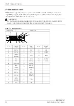
Table 4.9 DVI-analog RGB conversion adapter
Connector type
DVI-I 29 pin
1
8
17
24
16
C1
C2
C3
C4
C5
5
1
6
10
11
15
15.00
[mm]
6.20
5.80
39
.40
30.00
33
.00
Signal on analog RGB
Pin No.
Pin No.
Pin No.
Pin No.
1 RED 9 +5V
2 GREEN 10 GND
3 BLUE 11 N.C.
4 N.C. 12
DDC
DATA
5 GND 13
HSYNC
6 GND 14
VSYNC
7 GND 15
DDC
CLK
8 GND
Display driver
Install the appropriate audio driver for your OS from the CONTEC’s Web site
CAUTION
-
For Windows Embedded Standard 2009, the primary display cannot be changed.
-
If you connect to the RGB connector displays that process the unused pins in a special manner, the
PC may not start.
-
For the Windows Embedded Standard 2009 RGB model (BX-955S-DC6311), the BIOS SETUP
screen is only displayed on the display that is connected to the RGB connector.
-
For Windows Embedded Standard 2009, you need to set the screen resolution if the display cable is
not connected to this DVI-D interface at OS startup, but connected after OS startup (hereinafter
referred to as “Late Insertion”).
-
On Windows Embedded Standard 7, if you start the OS and then connect the display cable, the
screen may not be displayed.
-
For the Windows Embedded Standard 7 model (BX-955SD-DC6312), the BIOS SETUP screen
may not be displayed when some RGB displays are connected. In this situation, connect a
different RGB display, and then set "Boot Display Type" to "CRT" on the "Intel IGD
Configuration" menu.


