Setup
AD12-64(PCI), AD12-16(PCI)
5
2.
Setup
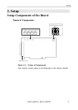
Setup Components of the Board
Names of Components
Signal connector
Board ID setting switch
SW1
BOARD ID
0
1
2
3
4
5
6
7 9
A
B
C
D
E
F
VR1 VR2 VR3 VR4
Analog input adjusting trimmers
Figure 2.1. Names of Components
Note that the switch setting in the illustration is the factory default.
Summary of Contents for AD12-16(PCI)
Page 1: ...AD12 64 PCI AD12 16 PCI 64 16 Channel Analog to Digital Input Board for PCI User s Guide...
Page 61: ...Functions and Operating Procedures AD12 64 PCI AD12 16 PCI 54...
Page 67: ...Calibration Procedures AD12 64 PCI AD12 16 PCI 60...
Page 71: ...System Reference AD12 64 PCI AD12 16 PCI 64...
Page 74: ...Index AD12 64 PCI AD12 16 PCI...
Page 75: ...A 46 068 LZJ3711 021011 991104...

