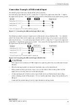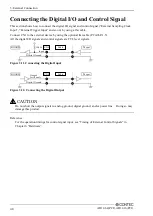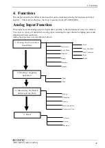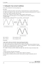
3. External Connection
AD12-64(PCI), AD12-16(PCI)
43
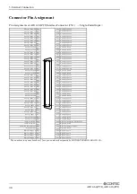
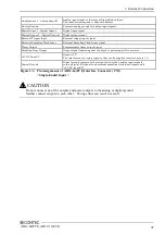
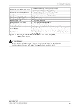
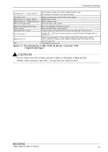
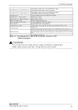
Analog Input 0[+] - Analog Input 7[+] Analog input signal at the time of Differential Input.
The numbers correspond to channel numbers.
Analog Input 0[-] - Analog Input 7[-]
Analog input signal at the time of Differential Input.
The numbers correspond to channel numbers.
Analog Ground
Common analog ground for analog input signals.
Digital Input 0 - Digital Input 3
Digital input signal.
Digital Output 0 - Digital Output 3
Digital output signal.
External Trigger Input
External trigger input signal.
External Sampling Clock Input
External Sampling Clock Input signal.
Timer Output
Programmable timer output signal.
Sampling Busy Output
Output signal indicating that the board is performing AD conversion
+5VDC from PC
5V.
The total current-carrying capacity that can be supplied from two pins is 1 A
Digital Ground
Digital ground common to those signals other than analog input signals, such as
digital I/O signals and external sampling clock input signals, and "+5V DC from
PC"
N.C.
No connection to this pin.
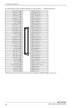
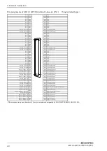
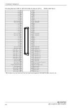
Figure 3.6. Pin Assignments of AD12-16(PCI) Interface Connector (CN1)
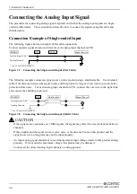
< Differential Input >
Do not connect any of the outputs and power outputs to the analog or digital ground.
Neither connect outputs to each other. Doing either can result in a fault.
CAUTION

