3. External Connection
44
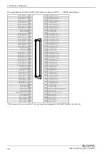
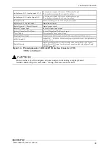
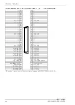
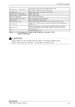
AD12-64(PCI), AD12-16(PCI)
Connecting the Analog Input Signal
The procedure for connecting analog signals depends on whether the analog input signals are single-
ended or differential. The sections below describe how to connect the signals using flat cable and
shielded cable.
Connection Example of Single-ended Input
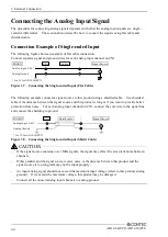
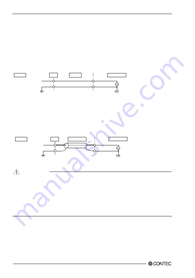
The following figure shows an example of flat cable connection.
Connect separate signal and ground wires for each analog input channel on CN1.
Figure 3.7. Connecting the Single-ended Input (Flat Cable)
The following example connects a signal source to this product using a shielded cable. Use shielded
cable if the distance between the signal source and this product is long or if you want to provide better
protection from noise. For each analog input channel on CN1, connect the core wire to the signal line
and connect the shielding to ground.
Figure 3.8. Connecting the Single-ended Input (Shield Cable)
-
If the signal source contains over 1MHz signals, the signal may effect the cross-talk noise between
channels.
-
If this product and the signal source receive noise or the distance between this product and the
signal source is too long, data may not be input properly.
-
An input analog signal should not exceed the maximum input voltage (relate to this product analog
ground). If it exceeds the maximum voltage, this product may be damaged.
-
Connect all the unused analog input channels to analog ground.
Analog Input 0..63 *
Analog Ground
BOARD
CN1
Cable
Signal Source
* 0 to 15 for AD12-16(PCI)
* 0 to 15 for AD12-16(PCI)
Analog Ground
Shield cable
Analog Input 0..63 *
BOARD
CN1
Signal Source
CAUTION

