1. Before Using the Product
AD12-64(PCI), AD12-16(PCI)
1
1.
Before Using the Product
About the Board
AD12-64(PCI) and AD12-16(PCI) are PCI-compliant interface boards that convert analog input signals
to digital equivalents (performing analog-to-digital conversion).
AD12-64(PCI) and AD12-16(PCI) can perform A-D conversion at a conversion speed of 10
µ
sec
[100KSPS] per channel and a resolution of 12bit.
Using the dedicated library VI-DAQ makes it possible to create each application for LabVIEW.
Features
Multi-channel analog input
< AD12-64(PCI) > can perform an analog input of single-ended input 64 channels and differential input
32 channels. < AD12-16(PCI) > can perform an analog input of single-ended input 16 channels and
differential input 8 channels.
Selection of single-ended input and differential input can be set up by the software.
Input range setup by software
Input range can be selected for each channel from the following ranges and can be set up by the
software.
±
10V,
±
5V,
±
2.5V,
±
1.25V, 0 - +10V, 0 - +5V, 0 - +2.5V, 0 - +1.25V
Sampling control function
The board can perform sampling either at arbitrary timings under control of software or periodically in
synchronization with a sampling clock signal.
The sampling clock signal can be selected between the internal one based on the on-board clock
generator and the external one using a digital signal input from an external source.
Digital input/output function
The board has four digital input and four digital output pins for TTL-level signals, allowing an external
device to be monitored and controlled.
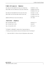
Optional units
Using optional units facilitates connections.
For more details on the option, please refer to this chapter “Cable & Connector” or
“Accessories (Option)”.


