3. External Connection
AO-1616L-LPE, AO-1608L-LPE
31
Digital I/O signals, Counter signals and Control
signals Connection
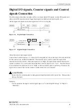
The following sections show examples of how to connect digital I/O signals, counter I/O signals, and
other control I/O signals (external trigger input signals, sampling clock input signals, etc.).
All the digital I/O signals and control signals are LVTTL level signals.
Figure 3.6. Digital Input Connection
Figure 3.7. Digital Output Connection
About the counter input signal control
Counter Gate Control Input (see “3. Connector Pin Assignment”) allows the input of the external clock
for the counter to be enabled and disabled. This function can be used to control the input of the
external clock for the counter. When the input level is “High”, the input of the external clock for the
counter is enabled. It is, on the other hand, disabled, when the input level is “Low”. Note that when it
is not connected, the input level is set to “High” as the board (card) pins are pulled up. Therefore, the
input of the external clock for the counter is enabled when it is not connected.
Do not short the output signals to analog ground, digital ground, and/or power line. Doing so may
damage the board.
Reference
For the operation timings for control signal input, see ”Control Signal Timings” in Chapter 6
“Hardware”.
Digital Input
Digital Ground
10k
Ω
BOARD
CN1
Cable
Target
Digital Ground
BOARD
CN1
Cable
Target
Digital Output
I
OL
=8mA
CAUTION


