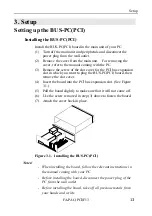
Major Parts of Each Component
FA-PAC(PCI)F13
11
Note!
The PCI bus expansion slots support a total of four interrupt pin
signals (INTA, INTB, INTC, INTD).
The individual slots have different wiring for connection not to
overload each IRQ line.
See the table below for the relationships among the PCI slot
numbers, bus numbers, device numbers, and interrupt pins.
Table 2.1. PCI Expansion Slot Numbers, Bus Numbers,
Device Numbers and Interrupt Pins
Slot No.
1
2
3
4
5
6
7
8
9
10
11
12
13
Bus No. (*1)
2
Device No.
4
5
6
7
4
5
6
7
6
4
5
6
7
INTA (*2)
INTB
INTC
INTD
A
B
C
D
D
A
B
C
C
D
A
B
B
C
D
A
D
A
B
C
C
D
A
B
B
C
D
A
A
B
C
D
C
D
A
B
B
C
D
A
A
B
C
D
D
A
B
C
C
D
A
B
*1:
*2:
5
4
3
This assumes that the PC's PCI slot in which the BUS-PC(PCI) has been plugged
has a bus number of 0 assigned.
This assumes that the PC's PCI slot in which the BUS-PC(PCI) has been plugged
has an array of interrupt pins INTA, INTB, INTC, and INTD.


