Ver.1.01
CNT-3204IN-USB
4
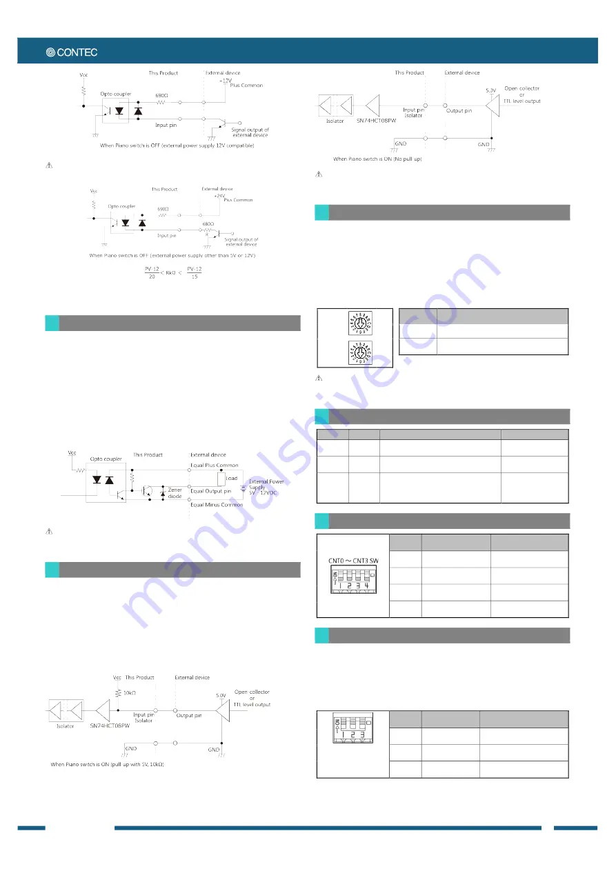
To use external power (other than 5V or 12V); insert a current limiting resistor at the R position.
The following expression is used to calculate current limiting resistance R with the external power supply as PV:
The expression is as follows;
If PV=24V, use a 600
Ω < R < 800Ω
resistor.
Control Output Circuit
The figure below shows the output circuit of control output section of
this product. The signal output section consists of an opto-coupler
isolated open collector output (current sink type). An external power
supply is therefore required to drive the output section of this product.
The maximum output current rating per channel is 50 mA for the
product.
Zener diodes are connected to the output transistor to protect against
surge voltages. As for the control output section, it is also possible to
output a one-shot pulse signal at the time of hardware event occurs,
such as a general-purpose output and count match.
-
Negative logic is set as default. (Negative logic is also set when setting is empty)
-
When the power is turned on, all output will be OFF.
Sampling Control Input Circuit
The figure below shows the circuit of signal input for sampling control
section of this product. These inputs are used for the start signal, the stop
signal and the clock signal of sampling operation. The signal input
section consists of a digital isolated and TTL input. This section can set
the pull-ups, so that the device that outputs a TTL level signal and also
the device that outputs an open-collector can be connected. The pull-up
voltage is 5V. If it is necessary to pull-up with different voltage such as
3.3V, turn off the pull-up setting and pull-up at the external device side.
Turn on the pull-up setting when sampling control input is not used. It may affect the unconnected control
input terminal when pull-up voltage is not connected.
Setting Switches
There are two setting switches. “x16” and “x1” represent high bits and low
bits of Module ID respectively.
Factory settings “00” can be used when only one device per model is
connected to one computer. Each device should be assigned a unique
Module ID in the range of 00 - 7Fh when several devices with the same
model are being connected.
Module ID
(x16)
[0]
Module ID
Setting description
00 - 7Fh
It is a setting range for module IDs.
Module ID
(x1)
[0]
FFh
Use only when upgrading the firmware.
Module ID 00h (Factory settings)
When setting with Module ID(x1) = F, Module ID(x16) = F, Module ID is only used for upgrading the firmware.
This setting cannot be used to distinguish or keep tracks of the devices.
LED Indicator
LED name
LED color
Status
Description
POWER
Green
OFF : Power-OFF
ON :
Power-ON
Display power status
A, B, DI
Yellow
OFF : Input-OFF
ON : Input-ON
Input status
Z
Yellow
Positive logic
OFF : Input-ON
ON : Input-OFF
Negative logic OFF : Input-OFF
ON : Input-ON
Input status
Input Resistance Setting Switch
Factory settings: All set to
OFF
Switch
number
Input signal
Setting description
1
General-purpose input
ON :
5V, 220
Ω
OFF :
12V, 690
Ω
2
Phase-Z input
ON :
5V, 220
Ω
OFF :
12V, 690
Ω
3
Phase-B input
ON :
5V, 220
Ω
OFF :
12V, 690
Ω
4
Phase-A input
ON :
5V, 220
Ω
OFF :
12V, 690
Ω
Pull-Up Setting Switch
5V pull-up of input signals for sampling control can be enabled or
disabled with the piano switch equipped on the bottom face of the
product. Set the switch to OFF when the other voltage such as 3.3V is
used, and pull-up externally. And set the switch to ON when the input
signals for sampling control are not used.
Factory settings: All set to ON
Switch
number
Input signal
Setting description
1
External sampling start
signal
ON :
Pull-up with 5V, 10k
Ω
OFF :
No pull-ups
2
External sampling
stop signal
ON :
Pull-up with 5V, 10k
Ω
OFF :
No pull-ups
3
External sampling
clock signal
ON :
Pull-up with 5V, 10k
Ω
OFF :
No pull-ups
S
CAUTION
CAUTION
CAUTION
CAUTION
PLUG-IN Electronic GmbH • Am Sonnenlicht 5 • 82239 Alling • Tel.: +49 (0) 8141 3697-0 • info@plug-in.de • www.plug-in.de


