4. Functions
56
CNT-3208M-PE
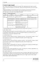
Control output signal
One control output signal is provided for each channel. The output signal can be used as a general-
purpose output (level output) or a one-shot pulse output for reporting a hardware event to an external
device.
Although all hardware events can be reported by the one-shot pulse output, that event cannot be
identified which results in the one-shot pulse output. Check the status in such cases.
The output logic is set with the on-board DIP switch(SW2).
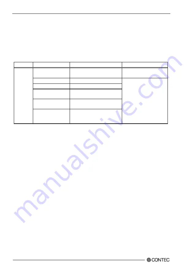
Table 4.8. Control output signal
Item
Purpose
Condition
Note
Control
output signal
General-purpose output
Software command
Level output
(Positive logic/Negative logic)
Count match(Register 0)
Count value = Comparison register 0 A one shot pulse is outputted.
(Positive logic/Negative logic) *1
Count match(Register 1)
Count value = Comparison register 1
Abnormal input error
When phases-A and B are changed at
the same time
Digital filter error
When a pulse faster than the digital
filter setting is input
Disconnection alarm error When a high-level signal is input to
both of the positive and negative
differential line receiver inputs
*1 The one-shot pulse width is set by software to 10
µ
sec, 100
µ
sec, 1 msec, 10 msec, or 100 msec.
General-purpose output
When the control output signal is not used for a hardware event, the control output pin can be used as a
general-purpose output. In this case, it is not a one-shot pulse output but a level output. It can be
switched between positive logic and negative logic.
Count match (Register 0)
When the count value matches the value in comparison register 0, a one-shot pulse is output as a count
match (register 0) output. It can be switched between positive logic and negative logic.
Count match (Register 1)
When the count value matches the value in comparison register 1, a one-shot pulse is output as a count
match (register 1) output. It can be switched between positive logic and negative logic.
Abnormal input error
When both of phase-A and B change at the same time, a one-shot pulse is output as an abnormal input
error. It can be switched between positive logic and negative logic.
Digital filter error
When a pulse faster than the digital filter time setting, a one-shot pulse is output as a digital filter error.
It can be switched between positive logic and negative logic.
Disconnection alarm error
When a high-level signal is received at both of the positive and negative differential line receiver inputs,
a one-shot pulse is output as a discontinuity alarm error. Both of the inputs go high upon detection of
discontinuity or an alarm output from the differential line receiver input circuit. It can be switched
between positive logic and negative logic.
Summary of Contents for CNT-3208M-PE
Page 7: ...vi CNT 3208M PE ...
Page 15: ...1 Before Using the Product 8 CNT 3208M PE ...
Page 30: ...2 Setup CNT 3208M PE 23 3 Click on the End button to finish condition setting Click on End ...
Page 35: ...2 Setup 28 CNT 3208M PE ...
Page 71: ...4 Functions 64 CNT 3208M PE ...


