3. External Connection
CNT24-4(PCI)H
29
3.
External Connection
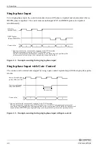
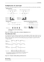
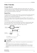
This chapter describes the interface connectors on the board and the external I/O circuits.
Check the information available here when connecting an external device.
Using the On-Board Connectors
Connecting a Board to a Connector
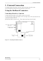
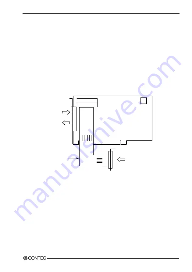
To input external pulse signals, use the interface connector on the board.
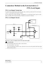
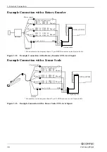
Use CN1 for the photo coupler isolated input. For TTL level input, connect CN2 to an external device by
connecting the optional cable CN2.
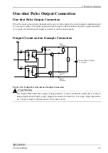
Matched pulse output is output from CN1. (Photo coupler isolated open collector output)
SW1
BOARD ID
CN2
CNT24-4(PCI)H
(CN1)
Photo coupler isolated input
(CH0 to CH3)
Matched pulse output
(CH0 to CH3)
Option cable
DT/B2
TTL level input
(CH0 to CH3)
Figure 3.1. Connecting the Interface Connector

