― 11 ―
Check Operation
(Digital I/O of the Integrated type)
1 2
3 4
5
6 7
8
9 1
0
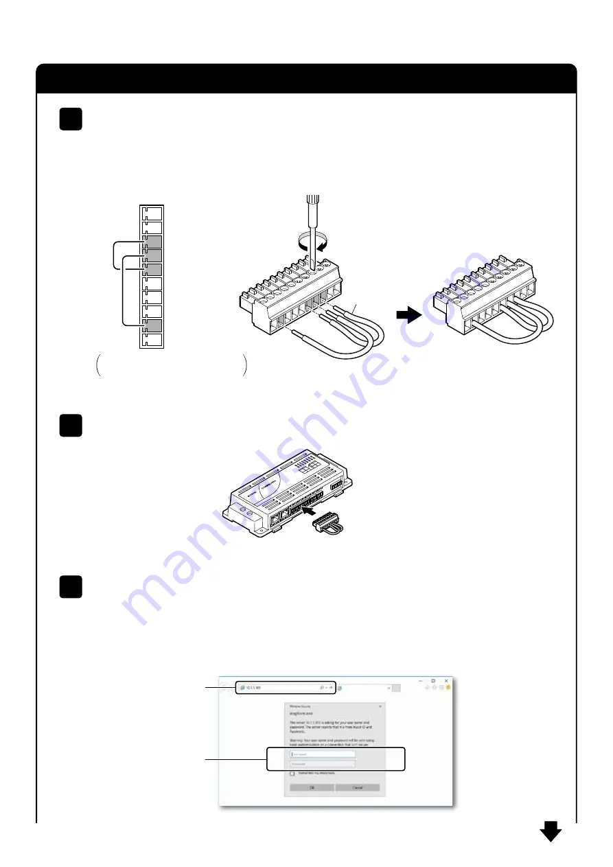
Connect the pin number 2 (DI0) and 7 (DO0+), then 6 (DI_MCOM) and 8 (DO0-) of the digital I/O
connector with the lead-wire to create the connector for operation check.
* The lead-wires are not included in the package. Please use the recommended wire, AWG28-16.
1
Place the operation check connector into the digital I/O connector of the controller.
2
Fasten the screws
with a driver to
secure the
lead-wires.
Lead-wires
Operation check connector
Go on to
the next page.
10
9
8
7
6
5
4
3
2
1
DO1-
DO1+
DO0-
DO0+
DI_MCOM
DI3/CNT1
DI2/CNT0
DI1
DI0
N.C.
Pin number
▼
Signal name
▼
This layout of connector pins is the example of the
multiple I/O model.
Please see an appropriate controller manual for
your model.
On your computer, start up Internet Explorer 11 and enter IP address (10.1.1.101) of the controller in
the address bar, then press [Enter].
The screen asking your user name and password appear. Enter them in the dialog box and click [OK]
to show Web browser menu.
3
10.1.1.101
User name
:
[Default setting]
mc341
Password
:
mc341


