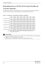

3. External Connection
32
DIO-48D-LPE
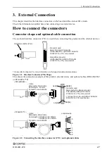
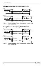
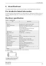
Example Connection 1 (Using DIO-68M/96F)
96 pin connector side
Cable
Signal source
GND
33
Ω
+3.3V
10k
Ω
External circuit
1-PA0 (A02 pin)
GND (A01 pin)
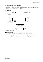
Input
Output
Target
Cable
+3.3V
GND
6.8k
Ω
2-PA0 (B02 pin)
GND (B01 pin)
SN74LV245
or equivalent
SN74LV245
or equivalent
96 pin connector side
External circuit
33
Ω
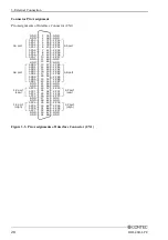
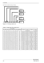
Figure 3.6. Connection Example Using 1-PA0 for Input and 2-PA0 for Output
(Using DIO-68M/96F)
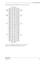
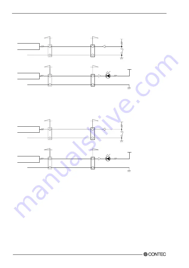
Example Connection 2 (Using PCA68PS-**P)
Cable
Signal source
GND
33
Ω
+3.3V
10k
Ω
1-PA0 (3 pin)
GND (2 pin)
Input
Output
Target
Cable
33
Ω
+3.3V
GND
6.8k
Ω
2-PA0 (37 pin)
GND (36 pin)
SN74LV245
or equivalent
SN74LV245
or equivalent
External circuit
External circuit
96 pin connector side
96 pin connector side
Figure 3.7. Connection Example Using 1-PA0 for Input and 2-PA0 for Output
(Using PCA68PS-**P)
Summary of Contents for DIO-48D-LPE
Page 7: ...vi DIO 48D LPE ...
Page 15: ...1 Before Using the Product 8 DIO 48D LPE ...
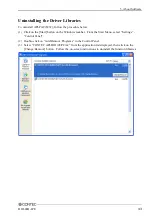
Page 33: ...2 Setup 26 DIO 48D LPE ...
Page 45: ...4 Function 38 DIO 48D LPE ...


