background image

5. BIOS Setup 


DS-280H Series User’s Manual 

31


Frequency/Voltage Control 

This section shows the user how to configure the processor frequency. 

Table 5.16.    Frequency/Voltage Control 

Phoenix – Award WorkstationBIOS CMOS Setup Utility

Frequency/Voltage Control 

Item Help 

  Spread Spectrun   

[Disabled] 


↑↓←→

  : Move Enter : /-/PU/PD : Value F10 : Save ESC : Exit F1:General Help 

F5 : Previous Values F6 : Fail-Safe Defaults F7 : Optimized Defaults 


Item 

Explanation 

Spread Spectrum 

This field sets the value of the spread spectrum. The default setting is Disabled.   
This field is for CE testing use only. 


Summary of Contents for DS-280H Series

Page 1: ...Digital Signage Player Athlon X2 2 8GHz SSD POSReady7 HDMIx4 DS 280H Series User s Manual CONTEC CO LTD ...

Page 2: ...DS 280H DC6413 Name Pcs The main body 1 AC adapter 1 AC cable 1 1 Product guide 1 Warranty Certificate 1 POSReady7 End User License Agreement 1 Setup Manual 1 Serial number label 1 GHOST End User License Agreement 1 Preinstall OS Recovery Procedures 1 Recovery Media 1 1 Do not use this AC power cable with any devices except for an attached AC adaptor Product Configuration Image See the Product Con...

Page 3: ... issues have been considered in the preparation of this document Should you notice an omission or any questionable item in this document please feel free to notify CONTEC CO LTD Regardless of the foregoing statement CONTEC assumes no responsibility for any errors that may appear in this document or for results obtained by the user as a result of using this product Trademarks Intel Intel Atom Intel...

Page 4: ... Information 3 Caution on the DS 280H Series 3 2 SYSTEM REFERENCE 5 Specification 5 Physical Dimensions 6 3 HARDWARE SETUP 7 Before Using the Product for the First Time 7 Hardware Setup 8 Installation Requirements 8 4 EACH COMPONENT FUNCTION 9 Component Name 9 Component Function 10 DC Power Input Connector DC IN 10 POWER SW POWER SW 10 Display Interface HDMI 10 USB Ports 10 Line in Interface LINE ...

Page 5: ...Features 18 Advanced Chipset Features 20 PCIE Configuration 21 IGX Configuration 22 Integrated Peripherals 23 Onboard Devices 24 OnChip SATA Device 25 OnChip Azalia Device 26 USB Device setting 27 Power Management Setup 28 PNP PCI Configurations 29 PC Health Status 30 Frequency Voltage Control 31 Defaults Menu 32 Supervisor User Password Setting 33 Exit Selecting 34 6 APPENDIX 35 Battery 35 7 LIST...

Page 6: ...has AMD Athlon II XLT V66C 2 8GHz TDP45W It supports applications which require high speed processing Dual configuration with discrete GPU and GPU which features integrated chipset This product is equipped with discrete GPU Radeon E4690 and GPU Radeon HD3200 which is integrated with AMD 780E chipset They support advanced graphics processing Major types of peripherals are supported with rich interf...

Page 7: ...y when this device is returned freight prepaid with a copy of the original invoice and a Return Merchandise Authorization to the distributor or the CONTEC group office from which it was purchased This warranty is not applicable for scratches or normal wear but only for the electronic circuitry and original products The warranty is not applicable if the device has been tampered with or damaged thro...

Page 8: ...ct supports an attached AC adapter and AC cable only WARNING Always check that the power supply is turned off before connecting or disconnecting power cables and other cables Users should not attempt to disassemble or modify this equipment or to replace components The manufacturer may not be able to provide service for equipment that has been modified by the user This product is not intended for u...

Page 9: ...ng burned do not touch the case while this product is in operation or immediately after turning off the power Avoid installation in a location where people may come into contact with the case CONTEC does not provide any guarantee for the integrity of data on any recording media such as SSD Always remove the power cable from the power outlet before changing hardware configurations such as the conne...

Page 10: ... ATA 1 slot 2 5inch SATA SSD 16GB SLC LAN 1port RJ 45 Connector Realtek RTL8111C PCI E Gigabit LAN Controller USB 4ports TYPE A Connector x 4 USB 2 0 compliant RS 232C 2port RJ 50 Connector RI Ring Indicator none Power Supply AC adapter specification This product supports an attached AC adapter and AC cable ONLY Input voltage 100V 240VAC 50 60Hz Input current 2A Rated output voltage 12VDC Rated ou...

Page 11: ...2 System Reference 6 DS 280H Series User s Manual Physical Dimensions Figure 2 1 Physical Dimensions ...

Page 12: ...ctly done again Check that AC plug is not connected then insert DC jack of AC adapter into the product Insert AC plug into AC inlet The product will wake up If you feel any abnormality after connection pull out AC plug quickly and then check if all installation was correctly done This product supports an attached AC adapter and AC cable ONLY STEP4 Set up BIOS By referring to Chapter 5 set up BIOS ...

Page 13: ...rements You can install this product on plastic LCD monitor wood drywall surface over studs or a solid concrete or metal plane directly Ensure the installer uses four M3 length 8mm screws to secure the system on wall Fasteners are not included with the unit and must be supplied by the installer The types of fasteners required are dependent on the type of wall construction ...

Page 14: ...t AC plug is not connected then insert DC jack of AC adapter into the product Insert AC plug into AC inlet The product will wake up POWER SW Power switch POWER LED Power ON display LED ACCESS LED Disk access display LED HDMI E4690 HD3200 Display HDMI x4 USB USB port connector x2 LINE IN Line in 3 5φ PHONE JACK LINE OUT Line out 3 5φ PHONE JACK LAN Ethernet 1000BASE T 100BASE TX 10BASE T RJ 45 conn...

Page 15: ... external HDMI output terminal of this unit HDMI cable You can connect HDMI output terminal of this product and HDMI input terminal of external video equipment with HDMI cable USB Ports This product is equipped USB 2 0 interface Table 4 2 USB Connector Pin No Signal name 1 USB_VCC 2 USB 3 USB 4 USB_GND Line in Interface LINE IN A line in connector is provided You can plug a microphone to this conn...

Page 16: ...provided Table 4 3 Giga bit Ethernet Connector Connector type RJ 45 Signal name Pin No 100BASE T 1000BASE T 1 TX TRD 0 2 TX TRD 0 3 RX TRD 1 4 N C TRD 2 5 N C TRD 2 6 RX TRD 1 7 N C TRD 3 8 N C TRD 3 LEDs for display of network statuses Right LED Link LED Opertion Green Blinking Left LED Operation LED 10M 100M Green 1000M Orange ...

Page 17: ...vided Table 4 4 Serial Port Interface Connector type RJ 45 Pin No Signal name 1 RTS Request to send 2 DTR Data terminal ready 3 TXD Transmit data 4 GND ground 5 DCD Data carrier detect 6 RXD Receive data 7 DSR Data set ready 8 CTS Clear to send CAUTION Do not Insert LAN Cable into Serial Port This product may malfunction or cause a failure ...

Page 18: ...ress F1 for help and press Esc to quit The following table provides more detail about how to navigate in the Setup program using the keyboard Table 5 1 Using Setup Key Function Up Arrow Move to the previous item Down Arrow Move to the next item Left Arrow Move to the item on the left Right Arrow Move to the item on the right Enter Move to the item you desired PgUp Increase the numeric value or mak...

Page 19: ...ghly understand To this end we strongly recommend that you avoid making any changes to the CPU defaults and the chipset defaults These defaults have been carefully chosen by both Insyde and your systems manufacturer to provide the absolute maximum performance and reliability Even a seemingly small change to them has the potential for causing you to be repaired A Final Note About Setup The informat...

Page 20: ... that a brief description of each highlighted selection appears at the bottom of the screen Table 5 2 Main Menu Display only Phoenix Award WorkstationBIOS CMOS Setup Utility Standard CMOS Features Advanced BIOS Features Advanced Chipset Features Integrated Peripherals Power Management Setup PnP PCI Configurations PC Health Status Frequency Voltage Control Load Fail Safe Defaults Load Optimized Def...

Page 21: ...rd CMOS Features Item Help Data mm dd yy Fri Aug 24 2012 Time hh mm ss 00 00 00 IDE Channel 0 Master None IDE Channel 0 Slave None IDE Channel 2 Master None IDE Channel 2 Slave None IDE Channel 3 Master None IDE Channel 3 Slave None Halt On No Errors Base Memory 640K Extended Memory 1833984K Total Memory 1835008K Move Enter Select PU PD Value F10 Save ESC Exit F1 General Help F5 Previous Values F6...

Page 22: ... system will stop and you will be prompted All But Keyboard The system boot will not be halted for a keyboard error it will stop for all other errors All But Diskette The system boot will not be halted for a disk error it will stop for all other errors All But Disk Key The system boot will not be halted for a key board or disk error it will stop for all others Halt On This field determines whether...

Page 23: ...ge will be displayed when trying to write on the boot sector or on the partition table on the disk which is typical of the virus CPU Internal and External Cache Cache memory is additional memory that is faster than conventional DRAM system memory CPUs from 486 type on up contain internal cache memory and most but not all modern PCs have additional external cache memory When the CPU requests data t...

Page 24: ...he default value is Setup When you select System the system prompts for the User Password every time you boot up When you select Setup the system always boots up and prompts for the Supervisor Password only when the Setup utility is called up APIC Mode APIC stands for Advanced Programmable Interrupt Controller The default setting is Enabled MPS Version Control for OS This option is specifies the M...

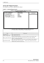
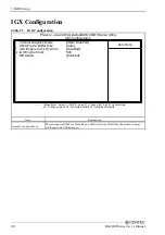
Page 25: ... Value F10 Save ESC Exit F1 General Help F5 Previous Values F6 Fail Safe Defaults F7 Optimized Defaults Item Explanation Init Display First The default setting is IGX NB Power Management The default setting is Auto Memory Hole At 15M 16M In order to improve performance certain space in memory can be reserved for ISA cards This memory must be mapped into the memory space below 16 MB The choices are...

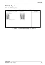
Page 26: ...lp Primary Dual Slot Config Enabled GPP Slots Power Limit W 25 GFX Port 1 Press Enter GFX Port 2 Press Enter GPP1 Press Enter GPP2 Press Enter GPP3 Press Enter GPP4 Press Enter GPP5 Press Enter GPP6 Press Enter NB SB Port Features Press Enter Move Enter Select PU PD Value F10 Save ESC Exit F1 General Help F5 Previous Values F6 Fail Safe Defaults F7 Optimized Defaults ...

Page 27: ...MA SidePort UMA Frame Buffer Size Auto IGX Engine Clock Override Disabled x IGX Engine Clock 500 NB Azalia Enabled Move Enter Select PU PD Value F10 Save ESC Exit F1 General Help F5 Previous Values F6 Fail Safe Defaults F7 Optimized Defaults Item Explanation Internal Graphics Mode The settings for IB828 are Disabled and UMA while the IB828 has additional settings of Sideport and UMA sideport ...

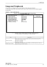
Page 28: ... SATA Device Press Enter OnChip Azalia Device Press Enter Onboard Serial Port 1 3F8 IRQ4 Onboard Serial Port 2 2F8 IRQ3 PWRON After PWR Fail On USB Device Setting Press Enter Move Enter Select PU PD Value F10 Save ESC Exit F1 General Help F5 Previous Values F6 Fail Safe Defaults F7 Optimized Defaults Item Explanation Onboard Serial Port These fields allow you to select the onboard serial ports and...

Page 29: ...nboard Devices Phoenix Award WorkstationBIOS CMOS Setup Utility Onboard Devices Item Help Onboard Realtek NIC Enabled Onboard Lan Boot ROM Disabled Move Enter Select PU PD Value F10 Save ESC Exit F1 General Help F5 Previous Values F6 Fail Safe Defaults F7 Optimized Defaults ...

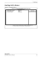
Page 30: ...TA Device Phoenix Award WorkstationBIOS CMOS Setup Utility OnChip SATA Device Item Help OnChip SATA Channel Enabled OnChip SATA Type IDE Combined Mode Disabled Move Enter Select PU PD Value F10 Save ESC Exit F1 General Help F5 Previous Values F6 Fail Safe Defaults F7 Optimized Defaults ...

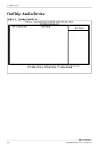
Page 31: ...ce Table 5 11 OnChip Azalia Device Phoenix Award WorkstationBIOS CMOS Setup Utility OnChip Azalia Device Item Help HD Audio Azalia Enabled Move Enter Select PU PD Value F10 Save ESC Exit F1 General Help F5 Previous Values F6 Fail Safe Defaults F7 Optimized Defaults ...

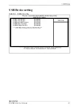
Page 32: ...ility USB Device Setting Item Help USB 1 0 Controller Enabled USB 2 0 Controller Enabled USB Keyboard Function Enabled USB Mouse Function Enabled USB Storage Function Enabled USB Mass Storage Device Boot Setting Move Enter Select PU PD Value F10 Save ESC Exit F1 General Help F5 Previous Values F6 Fail Safe Defaults F7 Optimized Defaults ...

Page 33: ...t for HDD Power Down which ranges from 1 min to 15 min HDD Power Down When enabled and after the set time of system inactivity the hard disk drive will be powered down while all other devices remain active Video Off Option This field sets the video off option By default video goes into suspend state and then Off Video Off Method This field defines the Video Off features There are three options V H...

Page 34: ...ed Defaults Item Explanation Reset Configuration Data This field allows you to determine whether to reset the configuration data or not The default value is Disabled Resources Controlled by This PnP BIOS can configure all of the boot and compatible devices with the use of a PnP operating system such as Windows 95 PCI VGA Palette Snoop Some non standard VGA display cards may not show colors properl...

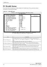
Page 35: ...xit F1 General Help F5 Previous Values F6 Fail Safe Defaults F7 Optimized Defaults Item Explanation Shutdown Temperature This field allows the user to set the temperature by which the system automatically shuts down once the threshold temperature is reached This function can help prevent damage to the system that is caused by overheating CPU Warning Temperature This field allows the user to set th...

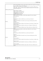
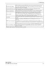
Page 36: ...ix Award WorkstationBIOS CMOS Setup Utility Frequency Voltage Control Item Help Spread Spectrun Disabled Move Enter Select PU PD Value F10 Save ESC Exit F1 General Help F5 Previous Values F6 Fail Safe Defaults F7 Optimized Defaults Item Explanation Spread Spectrum This field sets the value of the spread spectrum The default setting is Disabled This field is for CE testing use only ...

Page 37: ...mation dialog box with a message similar to Load Fail Safe Defaults Y N N Pressing Y loads the BIOS default values for the most stable minimal performance system operations Load Optimized Defaults When you press Enter on this item you get a confirmation dialog box with a message similar to Load setup Defaults Y N N Pressing Y loads the default values that are factory settings for optimal performan...

Page 38: ...ess Esc to abort the selection and not enter a password To disable a password just press Enter when you are prompted to enter the password A message will confirm the password will be disabled Once the password is disabled the system will boot and you can enter Setup freely PASSWORD DISABLED When a password has been enabled you will be prompted to enter it every time you try to enter Setup This pre...

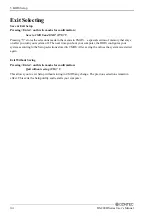
Page 39: ...ter you turn your system off The next time you boot your computer the BIOS configures your system according to the Setup selections stored in CMOS After saving the values the system is restarted again Exit Without Saving Pressing Enter on this item asks for confirmation Quit without saving Y N Y This allows you to exit Setup without storing in CMOS any change The previous selections remain in effe...

Page 40: ...Type Lithium primary battery Model BR2032 Maker Panasonic Nominal voltage 3V Nominal capacity 200mAh Lithium content 1g or less Removing the battery Remove the battery according to the following figure Figure 6 1 Removing the battery Disposing the battery Dispose the removed battery properly as instructed by local government ...

Page 41: ...6 Appendix 36 DS 280H Series User s Manual ...

Page 42: ... of Options DS 280H Series User s Manual 37 7 List of Options Display cable only for HDMI input IPC HDMI 015 HDMI Cable 1 5m Please check our website in order to know the latest information about our options ...

Page 43: ...odogawa ku Osaka 555 0025 Japan Japanese http www contec co jp English http www contec com Chinese http www contec com cn No part of this document may be copied or reproduced in any form by any means without prior written consent of CONTEC CO LTD 12212012 12212012 Management No NA02209 Parts No LYPQ381 ...

Reviews: