background image


3. Hardware Setup


User’s Manual 

17


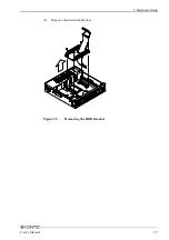
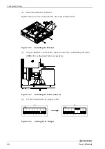
(2) 

Remove the hard disk bracket. 


Figure 3.2. 

Removing the HDD Bracket 

Summary of Contents for IPC-BX/M630 Series

Page 1: ...IPC Series BOX PC IPC BX M630 PCI Series User s Manual CONTEC CO LTD...

Page 2: ...issues have been considered in the preparation of this document Should you notice an omission or any questionable item in this document please feel free to notify CONTEC CO LTD Regardless of the foreg...

Page 3: ...0 Physical Dimensions 11 3 Hardware Setup 15 Before Using the BOX PC for the First Time 15 Hardware Setup 16 Removing the Top Cover and HDD Bracket 16 Locations and Settings of Internal Connectors and...

Page 4: ...48 Keyboard Interface 49 Mouse Interface 49 Serial Port Interface 50 Floppy Disk Interface 58 USB Ports 59 Ethernet 60 PC Card Slots 61 DVI Interface 62 Printer Port Interface 65 RAS Functions 66 Wat...

Page 5: ...iv User s Manual...

Page 6: ...a wide range of applications as a compact platform based on a general purpose PC OS As this series incorporates handpicked components such as the embedded types of CPU and chipset it excels in enviro...

Page 7: ...d by EEPROM IPC BX M630 PCI Series is compatible with IPC BX M600 PCW Series Compatible Operating Systems Windows 2000 Professional Windows NT Workstation 4 0 SP6a Windows XP Embedded Windows NT Embed...

Page 8: ...e CONTEC group office where you purchased before returning any product No product will be accepted by CONTEC group without the RMA number Liability The obligation of the warrantor is solely to repair...

Page 9: ...location exposed to extremely high or low temperature or susceptible to rapid temperature changes Example Exposure to direct sun In the vicinity of a heat source Do not use the product in extremely h...

Page 10: ...supply Estimated life is about 10 years based on continual operation at 40 C horizontal installation However higher operating temperatures will result in shorter life 2 Battery The internal calendar c...

Page 11: ...accordance with the instruction manual may cause harmful interference to radio communications Operation of this equipment in a residential area is likely to cause harmful interference at his own expe...

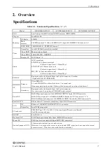
Page 12: ...DD or silicon disk drive 1 internal unit One more unit can be added Either of the two must be a silicon disk drive IDE HDD I F Secondary Equipped with a dedicated 40pin half pitch connector for connec...

Page 13: ...ply capacity None 5V 2A 1A x 2 Slot 5V Not supplied 12V 0 5A 12V 80mA 5V 4A 1A x 4 Slot 5V Not supplied 12V 0 5A 12V 80mA Physical dimensions mm 262 W 262 D 55 H 262 W 262 D 115 H 262 W 262 D 180 H We...

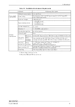
Page 14: ...ive gases None Line noise AC line 2kV Signal line 1kV IEC1000 4 4Level 3 EN61000 4 4Level 3 Line noise resistance Static electricity resistance Contact discharge 4kV IEC1000 4 2Level 2 EN61000 4 2Leve...

Page 15: ...ls PCMCIA types I II x 2 or III x 1 When three or more slots are needed select the C4P model To use five or more slots or a full size board connect the FA PA PC series Expansion slot CP and C4P models...

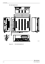
Page 16: ...2 Overview User s Manual 11 Physical Dimensions IPC BX M630 PCI C 55 302 284 262 262 170 126 56 68 5 20 4 5 2 R2 5 R5 5 228 17 17 mm 23 2 Figure 2 2 IPC BX M630 PCI C...

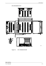
Page 17: ...2 Overview 12 User s Manual IPC BX M630 PCI CP 302 284 262 262 170 126 56 68 23 2 115 5 20 4 5 2 R2 5 R5 5 mm 228 17 17 Figure 2 3 IPC BX M630 PCI CP...

Page 18: ...2 Overview User s Manual 13 IPC BX M630 PCI C4P 302 284 262 262 170 126 56 68 23 2 180 mm 17 17 228 5 20 4 5 2 R2 5 R5 5 Figure 2 4 IPC BX M630 PCI C4P...

Page 19: ...2 Overview 14 User s Manual...

Page 20: ...power After verifying that you have correctly followed steps 1 and 2 turn on the power If you feel something is wrong after turning on the power turn off the power immediately and check to see if the...

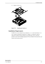
Page 21: ...ardware Setup Removing the Top Cover and HDD Bracket Before you start be sure that the power is turned off Remove only those screws that are explained Do not move any other screw 1 Remove the top cove...

Page 22: ...3 Hardware Setup User s Manual 17 2 Remove the hard disk bracket Figure 3 2 Removing the HDD Bracket...

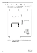
Page 23: ...ou remove the top cover and hard disk bracket the connectors jumpers and switches are laid out as shown in the figure below JP3 1 2 3 6 5 4 3 2 1 ON S1 8 7 M1 JP1 1 2 3 CN20 CN19 SERIAL3 CN16 SERIAL4...

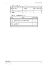
Page 24: ...OS JP3 Sets RS 485 termination 2 3 shorted 52 S1 Select the use of serial ports C and D 1 8 OFF 77 Table 3 2 Internal Connector List Name Function Reference page CN6 Primary IDE connector 44pin pin he...

Page 25: ...ing the cable through the hole on the base of the hard disk bracket fasten the disk to its bracket using four screws Fasten the disk using the outer or inner hole depending on the model you are using...

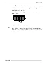
Page 26: ...using four screws 4 Close the top cover and secure it with screws Installing the Main Memory DIMM Compatible DIMM Types Obtain the following special option products Package type 144pin Small Outline...

Page 27: ...more memory install it to the socket on the front of the board Follow the next steps to fit the memory into the DIMM socket 1 Insert the DIMM into its socket with the notch positioned on the right si...

Page 28: ...dd more memory install it to the upper socket SO DIMM Disconnection Procedure Open the levers on both sides slightly to the left and right You should be able to remove the DIMM Lever Figure 3 6 Uninst...

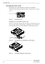
Page 29: ...e Screw Installing the AC Cord Metal Brace and the Clamp Insert the AC cord all the way into the inlet Fasten the AC cord metal brace using the screw you removed earlier Attach the clamp to an appropr...

Page 30: ...4 in place of RAS and PRINTER replace the bracket as follows 1 Be sure the power is turned off 2 Remove the top cover Figure 3 10 Removing the Top Cover 3 Remove the RAS PRINTER bracket Remove the tw...

Page 31: ...the bracket Figure 3 12 Installing the Bracket 5 Plug the SERIAL 3 and 4 cable connectors into CN16 SERIAL4 and CN19 SERIAL3 as illustrated below respectively Figure 3 13 Installing the Cable connecto...

Page 32: ...be installed in any orientation 1 3 Avoid orientation 4 6 since it might not adequately dissipate heat Similarly to maintain the ambient temperature within the range specified in the specifications e...

Page 33: ...3 Hardware Setup 28 User s Manual Installation Orientation 1 2 4 3 Connectors Wall Wall Connectors Wall Wall Floor Ceiling 5 6 Figure 3 16 Installation Orientation...

Page 34: ...Setup User s Manual 29 Distances between the BOX PC and Its Vicinity 100mm or more above 50mm or more side 50mm or more side 50mm or more back Connectors Figure 3 17 Distances between the BOX PC and I...

Page 35: ...3 Hardware Setup 30 User s Manual...

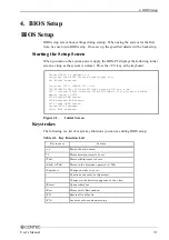
Page 36: ...x630 PCW series BIOS Ver x xx CPU Pentium III R Tualatin 512K LP 133MHz 1 150 processor 800MHz Memory Speed PC133 635K System RAM Passed 509M Extended RAM Passed 512K Cache SRAM Passed System BIOS Sh...

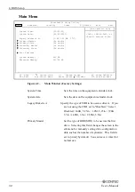
Page 37: ...tem Specific Help Tab Shift Tab or Enter selects field Figure 4 2 Main Window Factory Settings System Time Sets the time on the equipment calendar clock System date Sets the date on the equipment cale...

Page 38: ...Master Normally connection is not allowed Set this field if you have connected a CD ROM drive to the secondary IDE connector Secondary Slave Connection not allowed Set to None Boot Features This fiel...

Page 39: ...dow Factory Settings Floppy check Select whether to seek the FDD for a connection check during system boot up If no FDD has been connected with this field set to Enabled the BIOS suspends system boot...

Page 40: ...4 4 Advanced Window Factory Settings Reset Configuration Data Resets the system configuration data stored in BIOS ROM The data will be reset by setting this field to Yes and exiting BIOS Setup while...

Page 41: ...timer output to PO2 enabled set the output status in the power on state WDT Time up State With the watchdog timer output to PO2 enabled set the output status in the Time up state PCIC Irq Mode Set to...

Page 42: ...xit PhoenixBIOS Setup Utility Item Specific Help Advanced I O Device Configuration Configure port using options Disabled No configuration Enabled User configuration Figure 4 5 I O Device Configuration...

Page 43: ...ss Set to base I O address Interrupt Set to IRQ Mode Set to parallel port s operating mode DMA channel This is the DMA channel setting used when ECP is selected during parallel port mode setting Flopp...

Page 44: ...ecurity Window Factory Settings Set Supervisor Password Specify whether or not to require a password during setup If a password is set Supervisor Password is is enabled Supervisor mode allows all sett...

Page 45: ...dow Factory Settings Enabled ACPI Set to No ACPI Suspend Mode Set to Disabled APM Capabilities Set to Disabled Power Savings Specify whether or no to use power saving mode Choose from Disabled Customi...

Page 46: ...Item Specific Help Figure 4 8 PC Health Window Factory Settings Hardware Monitor Setup Start Hardware Monitor Setup as shown above Although you can make fan settings leave this field at the default b...

Page 47: ...ables a device and moves the device up or down n May move removable device between Hard Disk or Removable Disk d Remove a device that is not installed Figure 4 9 Boot Window Specify the order in which...

Page 48: ...ure 4 10 Exit Window Exit Saving Changes Saves values that have been modified on the setup screen in CMOS EEPROM and restarts the system Exit Discarding Changes Restarts the system using the previous...

Page 49: ...4 BIOS Setup 44 User s Manual...

Page 50: ...Slot1 2 UTP Ethernet HDD LED POWER LED SERIAL2 SERIAL1 DVI USB FD RAS KEYBOARD POWER SW AC INLET TOP COVER LINE IN LINE OUT MIC RESET IPC BX M630 PCI CP MOUSE PRINTER POWER LED SERIAL2 SERIAL1 DVI US...

Page 51: ...IAL1 DVI USB FD RAS KEYBOARD PCMCIA Slot1 2 POWER SW AC INLET TOP COVER LINE IN LINE OUT MIC UTP Ethernet RESET HDD LED Expansion slot PCI x 4 Figure 5 1 Component Identification 1 2 Side view IPC BX...

Page 52: ...nd C4P models DVI DVI connector 29pin DVI I PRINTER 1 Parallel port connector 25pin female D SUB RAS 1 RAS function and RS 485 connector 15pin female D SUB SERIAL3 1 Serial port 3 connector 9pin male...

Page 53: ...d named LINE OUT 3 5 mm stereo mini jack You can plug a headphone or amplifier integrated speakers into this connector MIC input Interface A MIC input connector is provided named MIC 3 5 mm stereo min...

Page 54: ...MD DS12300 14S 14 JST Pin No 1 2 3 4 Pin No 5 6 SHIELD Signal KBD DATA N C GND 5 0V DC Signal KBD CLK N C GND 6 4 2 1 3 5 Mouse Interface The BOX PC is equipped with a mouse connector named MOUSE MIN...

Page 55: ...SERIAL A and B I O Addresses and Interrupts COM I O address Interrupt 1 3F8h 3FFh 2 2F8h 2FFh 3 3E8h 3EFh 4 2E8h 2EFh IRQ 3 IRQ 4 The BIOS defaults to the following factory settings Serial port A COM...

Page 56: ...COM3 3E8h 3EFh IRQ5 Output connectors available with the SERIAL3 4 bracket The output connectors available with the SERIAL3 4 bracket mounted are RS 232C compliant serial ports same as the SERIAL 1 2...

Page 57: ...d The output connectors available with the SERIAL3 4 bracket mounted are RS 232C compliant serial ports same as the SERIAL 1 2 output connectors RS 422 RS 485 Specifications Transmission method RS 422...

Page 58: ...ntrol register Set I O address 4H bit 1 0 RTS is High Disable transmission 1 RTS is Low Enable transmission I O Addresses and Instructions The I O addresses and instructions of COM1 are shown next Tab...

Page 59: ...read received data from 03F8H DLL Divisor Latch LSB DLAB 1 D7 D6 D5 D4 D3 D2 D1 D0 bit7 MSB bit0 LSB Baud rate setting register LSB 03F8H D7 D6 D5 D4 D3 D2 D1 D0 bit7 MSB bit0 LSB Baud rate setting r...

Page 60: ...he receiving buffer is read Generated when the transmitter holding register is empty Cleared when the IIR is read or when transmitted data is written to THR Modem status interrupt is generated CTS DSR...

Page 61: ...loop back test 0 Disable 1 Enable LSR Line Status Regester 03FDH D7 D6 D5 D4 D3 D2 D1 D0 0 TEMT THRE BI FE PE OE DR Data ready 1 for existence of received data Overrun error 1 for occurrence of an err...

Page 62: ...is set by software by dividing the clock input 1 8432MHz The baud rate in terms of hardware can be set to a maximum of 115 200 bps The baud rates available in practice depend on the operating environ...

Page 63: ...t Input Pin No 2 4 6 8 10 12 14 16 18 20 22 24 26 Signal WRTPRT TRK0 GND WGATE GND GND STEP DIR MTR_ON N C DSKCHG N C 5V Direction Input Input Output Output Output Output Input 26 socket half pitch co...

Page 64: ...ual 59 USB Ports The BOX PC is equipped with two USB interface channels Table 5 13 USB Connector Pin No A1 A2 A3 A4 Signal USB0 Vcc USB0 Data USB0 Data USB0 GND Pin No B1 B2 B3 B4 Signal USB1 Vcc USB1...

Page 65: ...or Connector type RJ 45 Pin No 1 2 3 4 5 6 7 8 Signal TD TD RD N C N C RD N C N C Meamimg Transmitted data Transmitted data Received data Not connected Not connected Received data Not connected Not co...

Page 66: ...e A type III card should be inserted into slot 2 Attaching the Metal Brace to Keep the Card in Place Insert the front end Figure 5 4 Attaching the Metal Brace to Keep the Card in Place Power Supply to...

Page 67: ...y The connector is named DVI DVI I 29 pin connector Table 5 16 DVI Connector Connector DVI I 29pin 1 8 17 24 16 9 C1 C2 C3 C4 C5 Pin No Signal Pin No Signal Pin No Signal 1 DATA2 13 N C C1 RED 2 DATA2...

Page 68: ...rsion adapter Connector DVI I 29pin 1 8 17 24 16 C1 C2 C3 C4 C5 5 1 6 10 11 15 15 00 mm 6 20 5 80 39 40 30 00 33 00 Analog RGB signals Pin No Signal Pin No Signal 1 RED 9 HPD 2 GREEN 10 GND 3 BLUE 11...

Page 69: ...y driver IPC SLIB 01 for the OS running on your BOX PC For the download see Chapter 7 List of Options Serial Interface for Touch Panel Inside the LCD connector The BOX PC is equipped with a serial por...

Page 70: ...Pin No 1 2 3 4 5 6 7 8 9 10 11 12 13 Connector used on the unit Signal STRB D 0 D 1 D 2 D 3 D 4 D 5 D 6 D 7 ACK BUSY PE SELECT Meaning Enable data Data bit 0 Data bit 1 Data bit 2 Data bit 3 Data bit...

Page 71: ...signal External speaker ground RS 485 transmitting line RS 485 receiving line Minus common dedicated to PO2 General purpose output or watchdog timer alarm output General purpose output General purpose...

Page 72: ...value setting for the WDT counter port 4003h The watchdog timer stops by reading port 4002h The alarm out output is cancelled at the same time The alarm out is output from the RAS connector s PO2 WDT...

Page 73: ...ly Output data to ports 4001h and 4004h to set the counter clock NO BIOS setting Power ON Instruct WDT to stop Set timer value Start clear WDT Modify timer value Set event output control Application F...

Page 74: ...e output 1 Set the RAS connector s PO2 WDT 12 signal to alarm out Table 5 21 WD_S1 WD_S0 Alarm out Output Status Settings External alarm output status WD_S1 WD_S0 When power is turned off 1 When BIOS...

Page 75: ...nterrupt output at occurrence of WDT errors 0 0 1 Output to IRQ5 when time expires on the WDT 0 1 0 Output to IRQ7 when time expires on the WDT 0 1 1 Output to IRQ9 when time expires on the WDT 1 0 0...

Page 76: ...D5 D4 D3 D2 D1 D0 D7 WDT R Default XXXXXXX0b Figure 5 10 RAS Status Port 4005h R RAS status port WDT WDT status This is the WDT status bit This bit is cleared when the WDT stops read port 4002h 0 The...

Page 77: ...xed Input protection circuit Equipped with a reverse connection protection diode Input response time Less than 100 sec External circuit power supply 12 24VDC 10 Output Output specifications Open colle...

Page 78: ...0 0 1 Input the RAS connector s PI2 IRQ 14 signal to IRQ5 0 1 0 Input the RAS connector s PI2 IRQ 14 signal to IRQ7 0 1 1 Input the RAS connector s PI2 IRQ 14 signal to IRQ9 1 0 0 Input the RAS conne...

Page 79: ...sv R W Default XXXX0000b RE_GATE TE_GATE TE_SEL Figure 5 15 RS 485 Transmission and Reception Control Port 4007h TE_SEL Select the RS 485 transmission enable signal 0 Sets the RTS signal to the RS 485...

Page 80: ...re 5 16 Half Duplex Connection Method RX 11 RX 3 TX 10 TX 2 0 Controlled by RTS TE_SEL 1 Controlled by TE_GATE VCC TXD 47k 6 2k 0 Transmission prohibited RTS 1 Transmission permitted 0 Transmission pe...

Page 81: ...5 Each Component Function 76 User s Manual PO 0 2 NCOM External power Max 30VDC External circuit RAS connector PC817 Load 510 4 7k 2N3904 Figure 5 19 Output Circuit...

Page 82: ...Figure 5 20 Factory Settings Table 5 26 S1 Settings Bit ON OFF 1 Fixed at OFF system reserved 2 Fixed at OFF system reserved 3 Fixed at OFF system reserved 4 Fixed at OFF system reserved 5 Use SERIAL...

Page 83: ...25 27 29 31 33 35 37 39 41 43 Pin No 2 4 6 8 10 12 14 16 18 20 22 24 26 28 30 32 34 36 38 40 42 44 Signal RESET DD7 DD6 DD5 DD4 DD3 DD2 DD1 DD0 GND DDRQ DIOW DIOR IOCHRDY DDACK INTRQ DA1 DA0 CSI DACT...

Page 84: ...B17 B18 B19 B20 B1 B20 A1 A20 Connector in use Pin No A1 A2 A3 A4 A5 A6 A7 A8 A9 A10 A11 A12 A13 A14 A15 A16 A17 A18 A19 A20 Signal RESET DD7 DD6 DD5 DD4 DD3 DD2 DD1 DD0 GND DDRQ DIOW DIOR IOCHRDY DD...

Page 85: ...rea in the figure may not be mounted Power Supply to Expansion Slots The following table lists the voltage that can be supplied to a board in an expansion slot and the total current capacity of all sl...

Page 86: ...C BX M600 PCI CP 1 Be sure the power is turned off 2 Remove the top cover Figure 5 22 Removing the Top Cover 3 Remove the brace that holds the printed circuit board PCB down Remove the screws on the b...

Page 87: ...the slot and fasten it with screws Figure 5 24 Installation of an Expansion Board Note Make sure carefully that the board has been secured in the slot 5 Install the PCB brace It can hold down a board...

Page 88: ...5 Each Component Function User s Manual 83 6 Replace the expansion slot cover Figure 5 26 Replacing the Top Cover...

Page 89: ...Be sure the power is turned off 2 Remove the top cover Figure 5 27 Removing the Top Cover 3 Remove the brace that holds the printed circuit board PCB down Remove the screws on the brace The brace will...

Page 90: ...the slot and fasten it with screws Figure 5 29 Installation of an Expansion Board Note Make sure carefully that the board has been secured in the slot 5 Install the PCB brace It can hold down a board...

Page 91: ...5 Each Component Function 86 User s Manual 6 Replace the expansion slot cover Figure 5 31 Replacing the Top Cover...

Page 92: ...00000 00FFFFF 00E0000 00DFFFF 00CC000 00CBFFF 00C0000 00BFFFF 00A0000 009FFFF 0000000 Expansion memory area Main BIOS 128KB Expansion ROM area Free to the user VGA BIOS 48KB Video RAM area 128KB RAM 6...

Page 93: ...ondary 180 18F Reserved for system 190 1DF Available to user 1E8 1EF Reserved for system 1F0 1FF IDE hard disk controller Primary 200 277 Available to user 278 27F Reserved for parallel port LPT2 280...

Page 94: ...MASTER Timer 0 08H IRQ1 Keyboard 09H IRQ2 Interrupt controller 2 slave 0AH IRQ8 SLAVE Real time clock 70H IRQ9 Reserved for PCI device 71H IRQ10 Not in use 72H Available to user IRQ11 Serial port D CO...

Page 95: ...6 Appendix 90 User s Manual...

Page 96: ...C HDD40G 40GB hard disk drive Silicon disk drive IDE 2 5inch PC ESD500 A 512MB silicon disk drive PC ESD1000 A 1GB silicon disk drive PC ESD2000 A 2GB silicon disk drive PC ESD4000 A 4GB silicon disk...

Page 97: ...anel Link types IPC DT H40X PC T 15 0inch 1024 x 768 dots Panel mounted type IPC DT L40S PC T 12 1 inch 800 x 600 dots Panel mounted type IPC DT L440 PC TA 12 1 inch 800 x 600 dots Desktop wall mounte...

Page 98: ...l the driver is supplied with the OS or already installed on the PC 2 You can download the driver from the Download Library http www contec com download on the CONTEC web site If you need IPC SLIB 01...

Page 99: ...ogawa ku Osaka 555 0025 Japan Japanese http www contec co jp English http www contec com Chinese http www contec com cn No part of this document may be copied or reproduced in any form by any means wi...

Reviews: