background image


3. Outside Dimensions and Part Names 

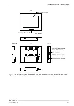
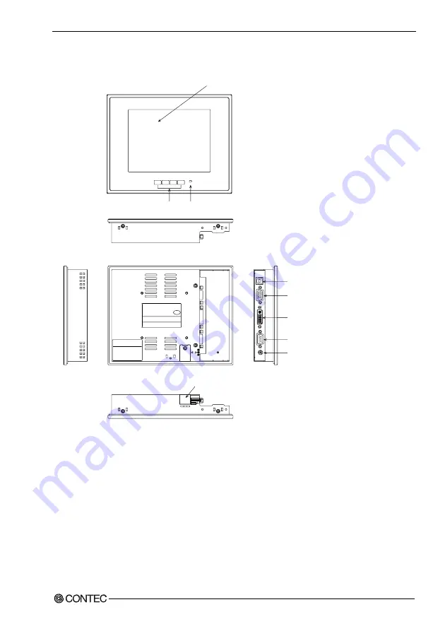
Part Names 


XXXXXXXXX

XXXXXXXXXXXXXXXXXX

SERIAL No. : XXXXXXXXXXXXX

MODEL :

XXXXXXXXX

XXXXXXXXX

CAUTION!

The screw bolting torque

of attachment must be

0.6N-m(MAX).

XXXXXXXXXXXXXXXXXX

INPUT :

Front

Back

Right side

Left side

Screen & Touch panel

Screen adjustment switch

AC adapter jack

Analog RGB connector

RS touch panel connector

USB touch panel connector

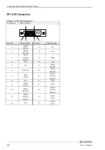
DVI-D connector

+12VDC power connector

PE

S C

N

T

I

PAS S

POWER LED

US

B

VG

A

DV

I

CO

M

1

2 12

VD

C-

IN

CAUTION!

12V DC-IN*1*2***

12V DC-IN simultaneously.

Don't connect 1 and 2  of

************

POWER

+

-

MENU

ESC


Figure 3.8.  Part Names(IPC-DT/S61VT-DC1) 


User’s Manual 

15


Summary of Contents for IPC-DT 61

Page 1: ...IPC Series Flat Panel Display IPC DT 61 Series User s Manual CONTEC CO LTD...

Page 2: ...ce All relevant issues have been considered in the preparation of this document Should you notice an omission or any questionable item in this document please feel free to notify CONTEC CO LTD Regardl...

Page 3: ...ns 7 General Specifications 9 Optical Display Specifications 10 3 Outside Dimensions and Part Names 11 Outside Dimensions 11 Part Names 15 Analog RGB Connector 18 RS Touch Panel Connector 18 USB Touch...

Page 4: ...ector 32 AC Adapter Jack 33 AC adapter code removal prevention fitting 34 7 Screen Adjustment and a Setup 35 Menu Screen 35 Direct Key 40 Memory of a Setting Value 40 8 LED Indicators 41 9 Touch Panel...

Page 5: ...iv User s Manual...

Page 6: ...els are supported when using the USB touch panel interface Auto scaling feature that resizes the input screen to the LCD dot configuration On screen display setup menu facilitating screen adjustment D...

Page 7: ...n Merchandise Authorization to the distributor or the CONTEC group office from which it was purchased This warranty is not applicable for scratches or normal wear but only for the electronic circuitry...

Page 8: ...aviolet ray Example Exposure to direct sun In the vicinity of a heat source Some products require configuration settings Always check these requirements before use Also never set switches or jumpers t...

Page 9: ...al is 50 000 hours for all models Assuming continuous operation at 25 degrees centigrade 2 Touch panel The operating lifetime of the touch panel is at least 1 million touches as tested by mechanical t...

Page 10: ...lay will still work normally However on the following CONTEC panel computers multiple touch panels can be used together when connected via the USB interface IPC PT 630 Series IPC PT H630X PCI C IPC PT...

Page 11: ...1 Introduction 6 User s Manual...

Page 12: ...nalog positive polarity 0 7Vp p 75 Separate V H TTL positive negative polarity Horizontal 31 80kHz vertical 56 75Hz Incoming signal specification DVI D input Digital RGB complies with TMDS 2 Cable len...

Page 13: ...or 100 240VAC input Input power supply voltage 12VDC 5 Consumption current 1 3A Max 1 4A Max 1 6A Max 2 5A Max Consumption current power save mode 0 4A Max Table 2 3 Power Supply Specifications AC Inp...

Page 14: ...onforming to JIS C0040 and IEC68 2 6 Shock resistance 10 G in the X Y Z directions for 11 ms Half sine wave Conforming to JIS C0041 and IEC68 2 27 Table 2 5 Structure specification DC Input Type Speci...

Page 15: ...rome 50deg 70deg 70deg 60deg Surface brightness at center Display in white 300cd m2 400cd m2 350cd m2 260cd m2 1 Surface brightness is a numerical value in a display simple substance The brightness th...

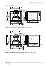
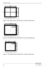
Page 16: ...g length 5mm Maximum tapping length 5mm ESC MENU POWER 12VDC IN 2 1 COM DVI VGA USB CAUTION 12VD C IN 1 2 12VD C IN sim ultaneous ly Don t connec t 1 and 2 of Figure 3 1 Outside Dimensions of Main Uni...

Page 17: ...75 100 27 5 6 5 75 Maximum tapping length 5mm Maximum tapping length 5mm COM USB DVI VGA ESC MENU POWER Figure 3 3 Outside Dimensions of Main Unit IPC DT L61SVT DC1 IPC DT H61XT DC1 mm Maximum tappin...

Page 18: ...ng length 5mm VGA DVI USB COM L N POWER MENU ESC Figure 3 5 Outside Dimensions of Main Unit IPC DT M61VT AC0 IPC DT L61SVT AC0 8 M4 TAP 302 54 5 5 21 5 41 5 242 40 3 67 4 67 5 148 256 96 8 189 5 251 3...

Page 19: ...DT H61XT AC0 V G A D V I U SB CO M L N 100 75 148 357 220 75 100 8 M4 TAP 288 67 4 69 3 21 41 8 5 POWER MENU ESC 233 309 376 123 305 mm Maximum tapping length 5mm Figure 3 7 Outside Dimensions of Main...

Page 20: ...X INPUT Front Back Right side Left side Screen Touch panel Screen adjustment switch AC adapter jack Analog RGB connector RS touch panel connector USB touch panel connector DVI D connector 12VDC power...

Page 21: ...ER LED Front Back Right side Left side Screen Touch panel Screen adjustment switch AC adapter jack Analog RGB connector RS touch panel connector USB touch panel connector VGA DV USB COM POWER MENU ESC...

Page 22: ...anel POWER LED AC power supply terminals Back Right side Left side Analog RGB connector RS touch panel connector USB touch panel connector COM USB DV VGA N L DVI D connector POWER MENU ESC Figure 3 10...

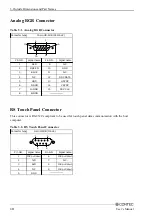
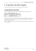
Page 23: ...D N C DDC DATA HSYNC VSYNC DDC CLK 15 pin HD SUB FEMALE 5 1 11 15 10 6 RS Touch Panel Connector This connector is RS 232C compliant to be used for touch panel data communication with the host computer...

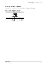
Page 24: ...l Connector The USB connector for communication between the host computer and touch panel Table 3 3 USB Touch Panel Connector Connector type Pin NO 1 2 Pin NO 3 4 Signal name 5V DATA Signal name DATA...

Page 25: ...Signal name Pin No Signal name 1 TMDS DATA2 13 N C 2 TMDS DATA2 14 5V 3 TMDS DATA2 SHIELD 15 GND 4 N C 16 HPD 5 N C 17 TMDS DATA0 6 DDC CLK 18 TMDS DATA0 7 DDC DATA 19 TMDS DATA0 SHIELD 8 N C 20 TXD...

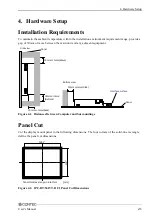
Page 26: ...sly Don t conn ec t 1 and 2 o f 30mm or more Side Interface surface Bottom view Panel 30mm or more above 30mm or more Bottom Side view 30mm or more back Panel Figure 4 1 Distances Between Computer and...

Page 27: ...M61VT AC0 Panel Cut Dimensions Panel thicknes range 1 6 to 7mm mm 1 0 R1 or less 243 303 1 0 Figure 4 4 IPC DT L61SVT DC1 IPC DT L61SVT AC0 Panel Cut Dimensions Panel thickness range 1 6 7mm R1 or les...

Page 28: ...panel Figure 4 6 Attaching the Fitting Used to Attach to the Main Unit 1 2 2 Hold the attach from the inside of the panel Panel Main body Overtightening screws may result in damage Example of figure I...

Page 29: ...4 Hardware Setup 24 User s Manual...

Page 30: ...endation Display Cable Model Maker Cable length KC V2 SANWA SUPPLY INC 2m KC V5 SANWA SUPPLY INC 5m If you use any other cable select a shielded cable the wire carrying the RGB and H Vsync signals and...

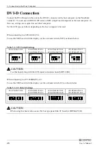
Page 31: ...itch Settings IPC DT S61VT DC1 IPC DT M61VT DC1 IPC DT M61VT AC0 IPC DT L61SVT DC1 IPC DT L61SVT AC0 IPC DT H61XT DC1 IPC DT H61XT AC0 1 2 3 4 ON 1 2 3 4 ON 1 2 3 4 ON 1 2 3 4 ON CAUTION Use this boar...

Page 32: ...able 5 5 S2 Switch Settings IPC DT S61VT DC1 IPC DT M61VT DC1 IPC DT M61VT AC0 IPC DT L61SVT DC1 IPC DT L61SVT AC0 IPC DT H61XT DC1 IPC DT H61XT AC0 1 2 3 4 ON 1 2 3 4 ON 1 2 3 4 ON 1 2 3 4 ON CAUTION...

Page 33: ...DVI connection after installation completes When connecting to a IPC BX M360 PCI C Series When using this box computer set the size of the connecting display by selecting Advanced Chipset Features Set...

Page 34: ...ouch panel to stop working Touch panel driver software is required to use the touch panel Purchase optional driver software IPC SLIB 01 for windows or IPC TPB1 DRV for MS DOS or download one from the...

Page 35: ...5 Connection to the Host Computer 30 User s Manual...

Page 36: ...ver supply power to both of them at the same time as it can cause a fault If you connect a power supply other than the option be sure to take safety measures for the power supply such as overvoltage p...

Page 37: ...tor type Model 12 VDC input connector B4PS VH manufactured by JST Pin No 1 2 3 4 Signal name GND GND 12V 12V 4 3 2 1 Applicable power cable connector Housing VHR 4N manufactured by JST Contact SVH 21T...

Page 38: ...nection AC Adapter Jack The AC adapter jack is used to connect the AC adapter IPC ACAP12 01 available as an option Do not connect any AC adapter other than the option 12V GND Figure 6 1 AC Adapter Jac...

Page 39: ...wer Supply Connection AC adapter code removal prevention fitting 1 Insert the plug of AC Adapter 2 Tighten the screws on the attachment fitting Figure 6 2 Code Removal Prevention Fitting 34 User s Man...

Page 40: ...press the MENU to save the settings S C R E E N M A N A G E R 6 4 0 x 4 8 0 6 0 0 H z C O N T R A S T D I S P L A Y A D J U S T C O L O R C O N T R O L O T H E R S T O U C H P A N E L I N P U T S O U...

Page 41: ...if the screen is offset or flickers after using AUTO SETUP despite adjusting with V POSITION Press or while checking the screen to optimize the position WIDTH Select this item to adjust the horizonta...

Page 42: ...he OSD screen can be adjusted Selecting this item displays a sub menu Use and to move between items and MENU to select Figure 7 4 OTHERS Sub Menu Screen OSD H POSITION Adjusts the horizontal position...

Page 43: ...ot work when the equipment is connected to the host with the touch panel driver already up and running or when the power to the equipment is recycled In suchcases set this item to ON enabled DISPLAY I...

Page 44: ...B A N A L O G R G B Figure 7 6 INPUT SOURCE Sub Menu Screen ANALOG RGB Displays the input from the ANALOG RGB connector DVI Displays the input from the DVI connector RESET Restores all settings to th...

Page 45: ...screen You can recover the screen from the power save mode by pressing any of the front switches The power consumption of the equipment in the power save mode is about 1 5 of that during normal opera...

Page 46: ...2 1 The LED looks like this when the equipment cannot process the input signal to provide normal display for example when the horizontal vertical sync signal frequency is exceeding the supported freq...

Page 47: ...8 LED Indicators 42 User s Manual...
Page 48: ...software is not bundled with this product Purchase the one separately or download it from the CONTEC s web site For further details refer to the READ_ME file for each driver Option touch panel driver...

Page 49: ...h device a different USB ID must be set on the DIP switch located on the side of each display unit USB ID7 USB ID0 POWER MENU ESC POWER MENU ESC 8 sets Max USB HUB RGB distributor Host PC USB cable RG...

Page 50: ...800 x 600 50 00 48 08 72 VESA 800 x 600 49 50 46 88 75 VESA 1024 x 768 65 00 48 36 60 VESA 1024 x 768 75 00 56 48 70 VESA 1024 x 768 78 75 60 02 75 VESA 1280 x 1024 108 00 63 98 60 VESA 1280 x 1024 1...

Page 51: ...T DC1 and IPC DT H61XT AC0 models The display is automatically enlarged if the input resolution is less than the LCD size and reduced if larger than the LCD size Note that as a result of enlarging or...

Page 52: ...PLDVI 050 Panel link DVI D conversion cable 5m IPC CBL3 2 Touch panel COM cable 2m IPC CBL3 5 Touch panel COM cable 5m Driver IPC SLIB 01 Driver Utility Soft Set CD ROM version Others IPC ACCODE3 AC p...

Page 53: ...ku Osaka 555 0025 Japan Japanese http www contec co jp English http www contec com Chinese http www contec com cn No part of this document may be copied or reproduced in any form by any means without...

Reviews: