Ver.1.12
PO-32B(PCI)H
3
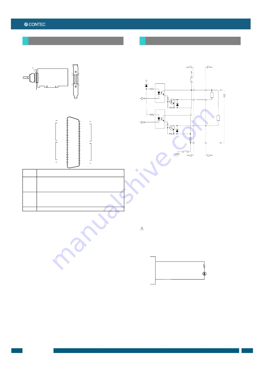
Connecting a Device to a Connector
To connect an external device to this board, plug the cable from
the device into the interface connector shown below.
Connector Pin Assignment
Pin Assignments of Interface Connector
O-00 - O-37
32 output signal pins. Connect output signals from the external device to these
pins.
P0, P1
When the external power supply is selected, its positive side is connected to this
pin.
When the internal power supply is used, this pin outputs power at +12 V. These
pins are common to 16 input signal pins.
N0, N1
When the external power supply is selected, its negative side is connected to this
pin.
When the internal power supply is selected, this pin serves as the ground.
These pins are common to 16 input signal pins.
N.C.
This pin is left unconnected.
Connect the output signals to a current-driven controlled device
such as a relay or LED. The board controls turning on/off the
current-driven controlled device using a digital value.
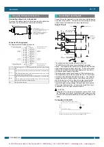
Output Circuit
The output circuits of interface blocks of the PIO-
16/16B(PCI)H and this product are illustrated the image
above. The signal output section as an Optocoupler isolated
open-collector output (current sink type). To drive the output
section, the on-board internal power supply must be used or
an external power supply is required.
The rated output current per channel is 100 mA at maximum.
The output section can also be connected to a TTL level input
as it uses a low-saturated transistor for output. The residual
voltage (low-level voltage) between the collector and emitter
with the output on is 0.5 V or less at an output current within
50 mA or at most 1.0 V at an output current within 100 mA.
To protect against surge voltage, a Zener diode is connected
to the output transistor. Also, an overcurrent protection circuit
is attached to a unit of eight output channels.
When the PC is turned on, all output are reset to OFF. See
the “Selecting the internal or external power supply” section
to connect the jumpers depending on the power supply to be
used.
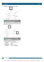
Connection to the LED
CN1
37
20
19
1
36
18
21
2
Interface connector (CN1)
- Connector used
37-pin D-SUB, female connector
DCLC-J37SAF-20L9 (mfd. by JAE) equivalent
Thumb screw: UNC#4-40 (inch screw)
- Applicable connectors
17JE-23370-02(D8C) (mfd. by DDK, Male),
FDCD-37P (mfd. by HIROSE, Male),
DC-37P-N (mfd. by JAE, Male),
or equivalent
1
2
3
4
5
6
7
8
9
10
11
12
13
14
15
16
17
18
19
N0
O-00
O-01
O-02
O-03
O-04
O-05
O-06
O-07
O-10
O-11
O-12
O-13
O-14
O-15
O-16
O-17
P0
N.C.
20
21
22
23
24
25
26
27
28
29
30
31
32
33
34
35
36
37
N1
O-20
O-21
O-22
O-23
O-24
O-25
O-26
O-27
O-30
O-31
O-32
O-33
O-34
O-35
O-36
O-37
P1
+0 port
(output)
+1 port
(output)
+2 port
(output)
+3 port
(output)
Common plus pin for
+0/+1 output ports
Common plus pin for
+2/+3 output ports
Common minus pin for
+2/+3 output ports
Common minus pin for
+0/+1 output ports
Vcc
JP2
<PIO-16/16B(PCI)H>
JP2/JP4 <PO-32B(PCI)H>
JP1
<PIO-16/16B(PCI)H>
JP1/JP3 <PO-32B(PCI)H>
+12V
Board
External device
Plus
common
Minus
common
Output pin
Output pin
Load
Load
External
power supply
12 - 24VDC
Zener
diode
Zener
diode
Over current protection
Optocoupler
Optocoupler
CAUTION
Output plus common (CN1 : 37pin)
B
oa
rd
When "1" is output to a relevant bit, the corresponding LED comes on.
When "0" is output to the bit, in contrast, the LED goes out.
O-20(CN1 : 21pin)
5.1k
Ω
Using the On-board Connectors
Connecting Output Signals
PLUG-IN Electronic GmbH • Am Sonnenlicht 5 • 82239 Alling • Tel.: +49 (0) 8141 3697-0 • info@plug-in.de • www.plug-in.de


