6. Appendix
100
PT-955LX / LXF User’s manual
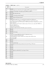
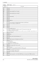
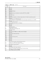
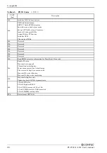
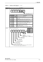
Table 6.5. Function of Each Register < 1 / 4 >
THR: Transmitter Holding Register [DLAB=0]
D7
D6
D5
D4
D3
D2
D1
D0
bit7
MSB
bit0
LSB
Register dedicated to write transmitted data to
03F8H
I/O address
Description
RBR: Reciever Buffer Register [DLAB=O]
D7
D6
D5
D4
D3
D2
D1
D0
bit7
MSB
bit0
LSB
Register dedicated to read received data from
03F8H
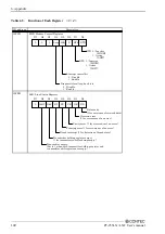
DLL: Divisor Latch (LSB) [DLAB=1]
D7
D6
D5
D4
D3
D2
D1
D0
bit7
MSB
bit0
LSB
Baud rate setting register (LSB)
03F8H
D7
D6
D5
D4
D3
D2
D1
D0
bit7
MSB
bit0
LSB
Baud rate setting register (MSB)
03F9H
IER: Interrupt Enable Register [DLAB=0]
D7
D6
D5
D4
D3
D2
D1
D0
0
03F9H
DLH: Divisor Latch (MSB) [DLAB=1]
0
0
0
EMS ELSI
ETHREI ERDAI
Received data
Interrupt enable
Received data register empty
Interrupt enable
Receiver line status
Interrupt enable
Modem status interrupt enable
[Always used at 0.]
1: Enable interrupt
0: Disable interrupt
Summary of Contents for PT-955LX-DC5000
Page 1: ...IPC Series PANEL PC 955 Series Fanless Atom N270 CF 12 1 model User s Manual CONTEC CO LTD...
Page 7: ...vi PT 955LX LXF User s manual...
Page 19: ...2 System Reference 12 PT 955LX LXF User s manual...
Page 29: ...3 Hardware Setup 22 PT 955LX LXF User s manual...
Page 39: ...4 Each Component Function 32 PT 955LX LXF User s manual...

