3. Hardware Setup
14
PT-955LX / LXF User’s manual
Hardware Setup
-
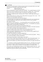
Before you start, be sure that the power is turned off.
-
Remove only those screws that are explained. Do not move any other screw.
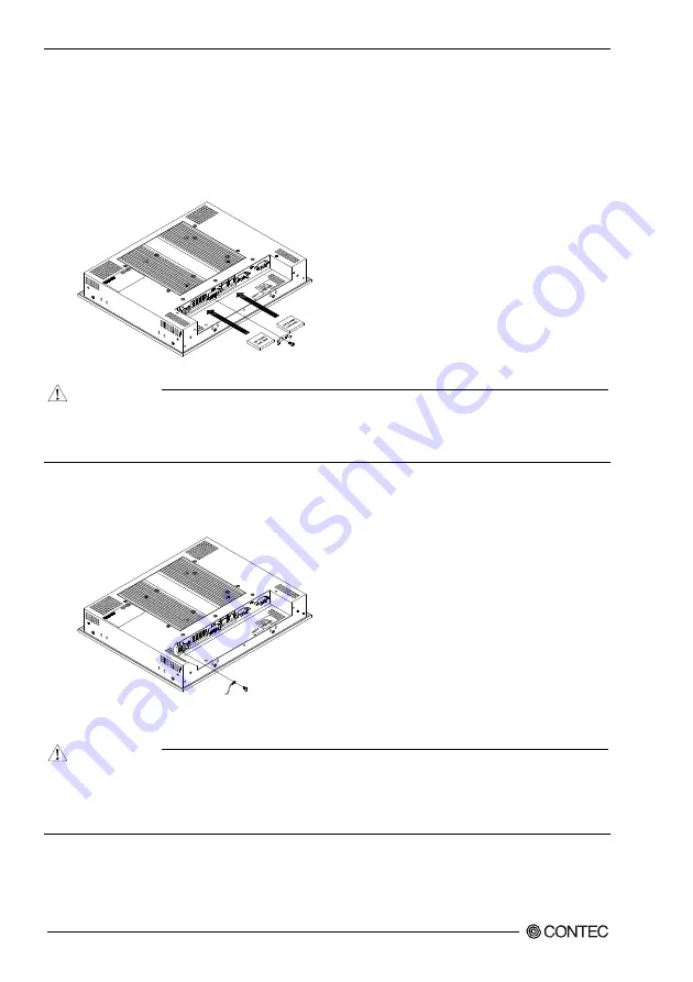
Attaching the CF Attachment Fittings
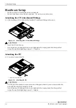
(1) After inserting a CF Card, fasten the bundled CF attachment fittings with a screw.
Figure 3.1. Attaching the CF Attachment Fittings
CAUTION
-
Insert the CF Card face up.
-
Screw holes may be damaged if screws are tightened with a torque greater than the specified
torque.The specified tightening torque is 3 - 3.5kgf
⋅
cm.
Attaching the FG
(1) Use screws to attach the FG.
* Attached screw (M3 x 8)
Figure 3.2. Attaching the FG
CAUTION
The FG pin of this product is connected to the GND signal of the DC power connector (DC-IN).
Note that the connection cannot be cut off.
Screw holes may be damaged if screws are tightened with a torque greater than the specified
torque.The specified tightening torque is 5 - 6kgf
⋅
cm.
Summary of Contents for PT-955LX-DC5000
Page 1: ...IPC Series PANEL PC 955 Series Fanless Atom N270 CF 12 1 model User s Manual CONTEC CO LTD...
Page 7: ...vi PT 955LX LXF User s manual...
Page 19: ...2 System Reference 12 PT 955LX LXF User s manual...
Page 29: ...3 Hardware Setup 22 PT 955LX LXF User s manual...
Page 39: ...4 Each Component Function 32 PT 955LX LXF User s manual...


