background image


1

Introduction


PT-955LX / LXF User’s manual 

1


1.


Introduction 

About the Product 

This product is a fanless PANEL-PC for embedded use based on Intel (R) Atom processor N270 and a 
945GSE (GMA950 incorporated) chipset.    Adoption of the long life power saving LED and Intel (R) 
Atom processor offers low power consumption while ensuring sufficient performance. 
    The “resource-saving PC” contributes downsizing and power-saving of equipment to reduce your 
running cost and to promote energy efficiency. 

It has extended interfaces such as 1000BASE-T, USB2.0, and serial.    It adopts CF card for the storage 
and is fanless, which demonstrate the totally spindleless design that simplifies the maintenance. 

Embedded-type CPU and chip set have been adopted.    The use of readily available parts ensures the ease 
of the use of the product.    In addition, the use of a Contec-customized BIOS allows support to be 
provided at the BIOS level. 

According to your application, two types (the panel mount type and the open frame type) are available. 


This product is available in the following 4 models: 

Base model and panel mount type equipped with Intel Atom Processor N270 1.60GHz 
PT-955LX-DC5000 (Memory 1GB, without OS, CF) 

OS-installed model and panel mount type equipped with Intel Atom Processor N270 1.60GHz 
PT-955LX-DC5311 (Memory 1GB, Windows Embedded Standard 2009 (Japanese version), CF 2GB) 

Base model and open frame type equipped with Intel Atom Processor N270 1.60GHz 
PT-955LXF-DC5000 (Memory 1GB, without OS, CF) 

OS-installed model and open frame type equipped with Intel Atom Processor N270 1.60GHz 
PT-955LXF-DC5311 (Memory 1GB, Windows Embedded Standard 2009 (Japanese version), CF 

2GB) 

Features 

Contributing to reduction of running cost and promotion of energy efficiency 

Power consumption is about 30% less compared to the conventional standard model 
(IPC-PT700HX-AC426). Due to adoption of the low power consumption LED backlight and Intel (R) 
Atom processor N270, low power consumption, approximately 41W*1 even at a high load condition, is 
achieved at the same time sufficient performance is ensured, contributing to the lesser running cost. 

*1 

Median value of power consumption of a standard model PT-955LX-DC5311 with input power of 
24VDC under unloaded and fully-loaded conditions.


Contributing to smaller device size. Small footprint with depth of 43.8mm*2. 

Depth is reduced by approximately 40% compared to the conventional standard model 
(IPC-PT700HX-AC426).    With our original heat release technology, the slim case with depth of 43.8mm 
is made offering fanless design (no use of a fan motor which has a finite life). This contributes to 
downsizing of the equipment. The mounting structure conforms to VESA standard 100 x 100 mm and can 
be mounted on a LCD arm. 

*2 

Dimension of PT-955LX-DC5311 not including the mounting bracket.


Summary of Contents for PT-955LX-DC5000

Page 1: ...IPC Series PANEL PC 955 Series Fanless Atom N270 CF 12 1 model User s Manual CONTEC CO LTD...

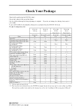
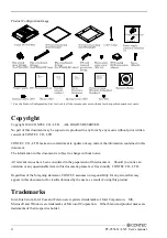
Page 2: ...ne None 2 2 The attachment fittings for PT955LXF short None None 2 2 CF card removal prevention fitting 1 1 1 1 1 1 Screws for attachment fittings Three point sems screw M4 x 8 None None 8 8 Screws M4...

Page 3: ...ion in this document is subject to change without notice All relevant issues have been considered in the preparation of this document Should you notice an omission or any questionable item in this doc...

Page 4: ...ons 4 Safety Information 4 Caution on the PT 955 Series 4 2 SYSTEM REFERENCE 7 Specification 7 Power Management Features 10 Power Requirements 10 Power Consumption 10 Physical Dimensions 11 3 HARDWARE...

Page 5: ...rting Setup 33 Using Setup 34 Getting Help 34 In Case of Problems 34 A Final Note About Setup 34 Main Menu 35 Setup Items 35 Standard CMOS Setup 37 Main Menu Selections 38 IDE Adapters 39 Advanced BIO...

Page 6: ...u 82 Supervisor User Password Setting 83 Exit Selecting 84 POST Messages 84 POST Beep 84 Error Messages 85 6 APPENDIX 91 Memory Map 91 I O Port Addresses 92 Interrupt Level List 93 POST Codes 94 COM I...

Page 7: ...vi PT 955LX LXF User s manual...

Page 8: ...y 1GB Windows Embedded Standard 2009 Japanese version CF 2GB Base model and open frame type equipped with Intel Atom Processor N270 1 60GHz PT 955LXF DC5000 Memory 1GB without OS CF OS installed model...

Page 9: ...x 2 It has 2 CF card slots that can use for OS and data They are very useful because you can use one slot for system start up and the other for maintenance system log or taking away the collected dat...

Page 10: ...when this device is returned freight prepaid with a copy of the original invoice and a Return Merchandise Authorization to the distributor or the CONTEC group office from which it was purchased This w...

Page 11: ...that the power supply is turned off before connecting or disconnecting power cables Procedures that could result in serious injury or loss of human life should never be performed from a touch panel U...

Page 12: ...ntegrity of data on CF Always disconnect the power cable from the receptacle before mounting or removing the expansion board or before connecting or disconnecting any connector To prevent corruption o...

Page 13: ...re rates 100 000 rewrite cycles 1 000 000 hours MTBF 3 Touch panel The operating lifetime of the touch panel is at least 1 million touches as tested by mechanical touching under 300g of force at a rat...

Page 14: ...8 1 280 x 1 024 1 360 x 768 1 400 x 1 050 16 770 000 colors Audio AC97 compliant LINE OUT x 1 MIC IN x 1 IDE Primary IDE Master Slave Max 2 devices CF card slot connection LAN 3 Intel 82573L Controlle...

Page 15: ...upply connector 12 24VDC 4 Input power supply voltage 10 8 31 2VDC Current consumption 12VDC 3 5A Typ 4 5A Max 24VDC 1 7A Typ 2 3A Max Power supply External device power supply capacity CF card slot 3...

Page 16: ...C68 2 6 compliant Impact resistance 30G half sine shock for 11 ms in x y and z directions JIS C60068 2 27 compliant IEC68 2 27 compliant Grounding Class D grounding SG FG continuity 5 For more details...

Page 17: ...ors Normal doze suspend and conserve modes Global and local device power control Power Requirements Your system requires a clean steady power source for reliable performance of the high frequency CPU...

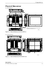
Page 18: ...2 System Reference PT 955LX LXF User s manual 11 Physical Dimensions PT 955LX DC5xxx Figure 2 2 Physical Dimensions PT 955LX DC5xxx PT 955LXF DC5xxx Figure 2 2 Physical Dimensions PT 955LXF DC5xxx...

Page 19: ...2 System Reference 12 PT 955LX LXF User s manual...

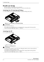
Page 20: ...es STEP3 Turn on the power After verifying that you have correctly followed steps 1 and 2 turn on the power If you find any abnormality after turning on the power turn it off and check to see if the s...

Page 21: ...TION Insert the CF Card face up Screw holes may be damaged if screws are tightened with a torque greater than the specified torque The specified tightening torque is 3 3 5kgf cm Attaching the FG 1 Use...

Page 22: ...le The system unit has a hole for attaching cable clamp Using a cable clamp for a cable with lock less connector such as the LINEOUT and USB Cable prevents the connector from being unplugged Use the c...

Page 23: ...igure 3 4 Dimensions of Panel Opening PT 955LX DC5xxx 2 Place the waterproof packing in the groove on the front face of the main body and insert the main body into the panel from the external side Fig...

Page 24: ...ons PT 955LXF DC5xxx 2 Use screws to attach the bundled attachment fittings with a screw Do not tighten screws with excess force Attached screw M3 x 8 Figure 3 2 Attaching the Attachment Fittings PT 9...

Page 25: ...using installation panel with screw holes Figure 3 9 Installation method PT 955LXF DC5xxx When using VESA standard 100mm mounting holes The main body has mounting holes according to VESA standard 100m...

Page 26: ...nstalled angle which is recommended 45 Installed angle of this product which is recommended is 0 45 Except for that the temperature specification of this product might not be filled Figure 3 11 Instal...

Page 27: ...between this product and its vicinity CAUTION Do not install this product into the fully sealed space except the case in which the internal temperature is adjustable by equipment such as air condition...

Page 28: ...mperature is decided from the multiple measurement points as shown below When making use of the product the air current should be adjusted to prevent that all the temperatures measured at the measurem...

Page 29: ...3 Hardware Setup 22 PT 955LX LXF User s manual...

Page 30: ...4 Each Component Function PT 955LX LXF User s manual 23 4 Each Component Function Component Name Bottom view PT 955LX DC5xxx PT 955LXF DC5xxx Figure 4 1 Component Name...

Page 31: ...ACK MIC IN Mic in 3 5 PHONE JACK LANA Ethernet 1000BASE T 100BASE TX 10BASE T RJ 45 connector LANB Ethernet 1000BASE T 100BASE TX 10BASE T RJ 45 connector USB USB port connector x 4 SERIALA Serial por...

Page 32: ...ntrols STATUS LED is available See the API description file mtdll_e chm included in RasUtility Samples in the CONTEC s Web site IPC SLIB 01 for details DC Power Input Connector DC IN To supply the pow...

Page 33: ...eakers into this connector Mic in Interface MIC A MIC input connector is provided You can plug a microphone to this connector for sound input Audio driver The audio driver is required to use the micro...

Page 34: ...Link LED Normal connection Green ON Operation Green Blinking Left LED Operation LED 10M Off 100M Green 1000M Orange LAN drivers Install the appropriate LAN driver for your OS from the CONTEC s Web sit...

Page 35: ...s and register function Table 4 6 SERIAL A B C D E I O Addresses and Interrupts SERIAL I O address Interrupt A 3F8h 3FFh IRQ 4 B 2F8h 2FFh IRQ 3 C system reserved 1 D system reserved 1 E system reserv...

Page 36: ...dditional display is different from that of the PANEL PC main display the size of screen images on the additional display will be decreased or increased with lower image quality When using the main un...

Page 37: ...atest version of IPC SLIB 01 check the CONTEC s Web site CAUTION You need to set the screen resolution if the display cable is not connected to this DVI D interface at OS startup but connected after O...

Page 38: ...hed off and the access LED is turned off Table 4 10 CF Card Connector Connector used on the product 50 socket header type 1 27mm pitch 50 25 26 1 Pin No Signal name Direction Pin No Signal name Direct...

Page 39: ...4 Each Component Function 32 PT 955LX LXF User s manual...

Page 40: ...n it finishes the BIOS will seek an operating system on one of the disks and then launch and turn control over to the operating system While the BIOS is in control the Setup program can be activated i...

Page 41: ...and return to Main Menu F1 key General help on Setup navigation keys F5 key Load previous values from CMOS F6 key Load the fail safe defaults from BIOS default table F7 key Load the optimized default...

Page 42: ...tems The main menu includes the following main setup categories Recall that some systems may not include all entries Standard CMOS Features Use this menu for basic system configuration Advanced BIOS F...

Page 43: ...IOS default values that are factory settings for optimal performance system operations While Award has designed the custom BIOS to maximize performance the factory has the right to change these defaul...

Page 44: ...5 2 Standard CMOS Setup The items in Standard CMOS Setup Menu are divided into 10 categories Each category includes no one or more than one setup items Use the arrow keys to highlight the item and the...

Page 45: ...er to enter the sub menu of detailed options IDE Channel 1 Master Options are in its sub menu Press Enter to enter the sub menu of detailed options IDE Channel 1 Slave Options are in its sub menu Pres...

Page 46: ...Selects the type of fixed disk User Type will let you select the number of cylinders heads etc Note PRECOMP 65535 means NONE Access Mode CHS LBA Large Auto Choose the access mode for this CF card Capa...

Page 47: ...BIOS Features Setup This section allows you to configure your system for basic operation You have the opportunity to select the system s default speed boot up sequence keyboard operation shadowing an...

Page 48: ...4 CPU Feature Press Enter to configure the settings relevant to CPU Feature Table 5 4 CPU Features Selections Description Choice Delay Prior to Thermal Select the interval to setup the delay timer fo...

Page 49: ...isable Bit When disabled forces the XD feature flag to always return 0 Hard Disk Boot Priority Figure 5 5 Hard Disk Boot Priority With the field there is the option to choose aside from the hard disks...

Page 50: ...arning message If you plan to run such a program we recommend that you first disable the virus warning Enabled Activates automatically when the system boots up causing a warning message to appear when...

Page 51: ...certain steps We recommend that you normally disable quick POST Better to find a problem during POST than lose data during your work USB Device Wait When USB devices which need longer time to be boote...

Page 52: ...mpts to load the operating system from the devices in the sequence selected in these items Boot Other Device The BIOS attempts to load the operating system from the devices in the sequence selected in...

Page 53: ...hen Disabled the following two items Typematic Rate and Typematic Delay are irrelevant Keystrokes repeat at a rate determined by the keyboard controller in your system When Enabled you can select a ty...

Page 54: ...ompt Note To disable security select PASSWORD SETTING at Main Menu and then you will be asked to enter password Do not type anything and just press Enter it will disable security Once the security is...

Page 55: ...problems and it must be ensured that the CF works with your system without problem before using this feature Also before performing backup read the licensing terms of your operating system carefully...

Page 56: ...herefore the backup CF can be used as it is in place of the current CF If backup is performed to a CF whose capacity is larger than the current CF the backup CF cannot be used as it is The backed up c...

Page 57: ...need to be altered The default settings have been chosen because they provide the best operating conditions for your system The only time you might consider making any changes would be if you discove...

Page 58: ...RAM RAS to CAS delay This field lets you insert a timing delay between the CAS and RAS strobe signals used when DRAM is written to read from or refreshed Fast gives faster performance and Slow gives m...

Page 59: ...cting Enabled allows caching of the system BIOS ROM at F0000h FFFFFh resulting in better system performance However if any program writes to this memory area a system error may result Video BIOS Cache...

Page 60: ...ess Root Port Function Table 5 7 PCI Express Root Port Function Selections Description Choice PCI Express Port 1 2 3 4 5 6 This item allows you to enable or disable or Auto configure the PCI Express P...

Page 61: ...GA Setting Selections Description Choice On Chip Frame Buffer Size When Enabled a fixed VGA frame buffer from A000h to BFFFh and a CPU to PCI write buffer are implemented DVMT Mode Allows you to set t...

Page 62: ...the LFP the display part of the main body is fixed to 1024 x 768 Notes This is the sole item shown Integrated Peripherals This section sets configurations for your hard disk and other integrated peri...

Page 63: ...tup 56 PT 955LX LXF User s manual OnChip IDE Device Figure 5 9 OnChip IDE Device Table 5 9 On Chip IDE Device Selections Description Choice HDD Select You can choose your CF card type to Auto Select o...

Page 64: ...ck mode most new drives do select Enabled for automatic detection of the optimal number of block read writes per sector the drive can support IDE DMA transfer access This item allows you to enable or...

Page 65: ...ce IDE Primary Master Slave UDMA UDMA Ultra DMA is a DMA data transfer protocol that utilizes ATA commands and the ATA bus to allow DMA commands to transfer data at a maximum burst rate of 33 MB s Whe...

Page 66: ...e supports In Auto mode the system automatically determines the best mode for the device IDE Secondary Master Slave UDMA UDMA Ultra DMA is a DMA data transfer protocol that utilizes ATA commands and t...

Page 67: ...ntroller Combined Mode Enable the combination of SATA and PATA Up to three IDE devices are available one for SATA and two for PATA Enhanced Mode Enable both SATA and PATA Up to three IDE drives are pr...

Page 68: ...5 BIOS Setup PT 955LX LXF User s manual 61 Description Choices SATA Port Set serial ATA channel to Primary Notes Only this item is displayed Onboard Device Figure 5 10 Onboard Device...

Page 69: ...Setting Table 5 11 On board device Selections Description Choice USB Over Current Support Enable or disable the USB Over Current In normal cases set it as Enabled USB 2 0 Controller Enable or disable...

Page 70: ...port Select Enabled when a USB keyboard has to be used on the OS that does not support USB Select Disabled for the OS that supports USB such as Windows XP USB Storage Function Select Enabled when usin...

Page 71: ...al Description Choice Onboard LAN A Select Enabled when using the Onboard LAN A controller Onboard LAN B Select Enabled when using the Onboard LAN B controller Onboard Lan Boot ROM Select Enabled when...

Page 72: ...55LX LXF User s manual 65 Super IO Device Figure 5 12 Super IO Device Table 5 12 Super I O device Selections Description Choice Onboard Serial Port A Select an address and corresponding interrupt for...

Page 73: ...s manual Description Choice Onboard Serial Port B Select an address and corresponding interrupt for the serial port B T P Serial Port Enable or disable touch panel serial port Select LFP when you use...

Page 74: ...re you system to most effectively save energy while operating in a manner consistent with your own style of computer use Figure 5 13 Power Management Setup Table 5 13 Power Management setup Selections...

Page 75: ...d the suspend mode respectively Use this category to select the type degree of power saving feature User Define Each mode can be set respectively Setting range of an enabled mode is 1 minute to 1 hour...

Page 76: ...swer to an incoming call to the modem select the interrupt request line IRQ To use this function it may be necessary to connect the Fax modem to the Wake On Modem connector of the keyboard computer Su...

Page 77: ...s the delay time to wait till the power button takes effect In Instant Off the power button takes effect immediately after pushed down In Delay 4 sec the power button needs to be pushed and held for 4...

Page 78: ...ow should be Enable alike Wake Up by PCI card Selecting Enable enables On board LAN WOL function Note that the PCI Express Wake setting below should be Enable alike Power On by Ring When set to Enable...

Page 79: ...5 BIOS Setup 72 PT 955LX LXF User s manual Description Choice Reload Global Timer Events When Enabled an event occurring on each listed device restarts the global timer for Standby mode...

Page 80: ...nterconnect is a system which allows I O devices to operate at speeds nearing the speed the CPU itself uses when communicating with its own special components This section covers some very technical i...

Page 81: ...mally you leave this field Disabled Select Enabled to reset Extended System Configuration Data ESCD when you exit Setup if you have installed a new add on and the system reconfiguration has caused suc...

Page 82: ...fic interrupt Such as IRQ4 for serial port 1 PCI ISA PnP Devices compliant with the Plug and Play standard whether designed for PCI or ISA bus architecture The Choice Legacy ISA and PCI ISA PnP Table...

Page 83: ...vices s using this INT Display Controller Bus 0 Dev 2 Func 0 USB 1 0 1 1 UHCI Controller Bus 0 Dev 29 Func 3 INT Pin 2 Assignment Devices s using this INT Multimedia Device Bus 0 Dev 30 Func 2 INT Pin...

Page 84: ...DE Controller Bus 0 Dev 31 Func 2 USB 1 0 1 1 UHCI Controller Bus 0 Dev 29 Func 1 SMBus Controller Bus 0 Dev 31 Func 3 INT Pin 5 Assignment Devices s using this INT Network Controller Bus 1 Dev 8 Func...

Page 85: ...in 8 Assignment Devices s using this INT USB 1 0 1 1 UHCI Controller Bus 0 Dev 29 Func 0 USB 2 0 EHCI Controller Bus 0 Dev 29 Func 7 PCI Express relative items Table 5 16 PCI Express Relative Items Se...

Page 86: ...5 BIOS Setup PT 955LX LXF User s manual 79 PC Health Status Figure 5 16 PC Health Status The BIOS shows the PC health status in this window...

Page 87: ...hen the temperature exceeds the value set in CPU Temperature Function above CPU THRM Throttling When the temperature exceeds the value set in CPU Temperature Function above the slot ring is activated...

Page 88: ...iption Choices Spread Spectrum When the system clock generator pulses the extreme values of the pulse generate excess EMI Enabling pulse spectrum spread modulation changes the extreme values from spik...

Page 89: ...tion dialog box with a message similar to Load Fail Safe Defaults Y N N Pressing Y loads the BIOS default values for the most stable minimal performance system operations Load Optimized Defaults When...

Page 90: ...s Esc to abort the selection and not enter a password To disable a password just press Enter when you are prompted to enter the password A message will confirm the password will be disabled Once the p...

Page 91: ...storing in CMOS any change The previous selections remain in effect This exits the Setup utility and restarts your computer POST Messages During the Power On Self Test POST if the BIOS detects an erro...

Page 92: ...and press Enter If you assumed the system would boot from the hard drive make sure the controller is inserted correctly and all cables are properly attached Also be sure the disk is formatted as a bo...

Page 93: ...r encountered initializing hard drive Hard drive cannot be initialized Be sure the adapter is installed correctly and all cables are correctly and firmly attached Also be sure the correct hard drive t...

Page 94: ...nce the last boot In EISA mode use Configuration Utility to reconfigure the memory configuration In ISA mode enter Setup and enter the new memory size in the memory fields Memory verify error at Indic...

Page 95: ...hen this error appears the system will boot in ISA mode which allows you to run the EISA Configuration Utility Slot not empty Indicates that a slot designated as empty by the EISA Configuration Utilit...

Page 96: ...d is locked P17 of keyboard controller is pulled low Keyboard error or no keyboard present Cannot initialize the keyboard Make sure the keyboard is attached correctly and no keys are being pressed dur...

Page 97: ...5 BIOS Setup 90 PT 955LX LXF User s manual...
Page 98: ...D0000h DFFFFh Expansion Area E0000h EFFFFh Extended System BIOS Area F0000h FFFFFh System BIOS Area 100000h FFFFFFFFh Extended Memory Area 00100000 Top of Main Memory Main DRAM Address Range Top of Ma...

Page 99: ...troller 2 00E0 00EF 16 bytes Reserved 00F0 00FF 16 bytes Arithmetic processor for numerical values 01F0 01F7 8 bytes Primary IDE controller 0274 0277 4 bytes Reserved ISA PnP 0279 0279 1 byte Reserved...

Page 100: ...2 slave 0AH IRQ8 SLAVE Real time clock 70H IRQ9 System reserved 71H IRQ10 Not in use Available for users 72H IRQ11 Not in use Available for users 73H IRQ12 Not in use Available for users 74H IRQ13 Co...

Page 101: ...Super I O chips 2 Enable keyboard interface 09h Reserved 0Ah 1 Disable PS 2 mouse interface optional 2 Auto detect ports for keyboard mouse followed by a port interface swap optional 3 Reset keyboard...

Page 102: ...tion Onboard clock generator initialization Disable respective clock resource to empty PCI DIMM slots Early PCI initialization Enumerate PCI bus number Assign memory I O resource Search for a valid VG...

Page 103: ...range 3 Initialize the APIC for P6 class CPU 4 On MP platform adjust the cacheable range to smaller one in case the cacheable ranges between each CPU are not identical 4Fh Reserved 50h Initialize USB...

Page 104: ...lated fields in 40 hardware 70h Reserved 71h Reserved 72h Reserved 73h Optional Feature Enter AWDFLASH EXE if AWDFLASH is found in floppy drive ALT F2 is pressed 74h Reserved 75h Detect install all ID...

Page 105: ...88h Reserved 89h Reserved 90h Reserved 91h Reserved 92h Reserved 93h Read HDD boot sector information for Trend Anti Virus code 94h Enable L2 cache Program boot up speed Chipset final initialization...

Page 106: ...R Receive buffer register RBR 03F8H 1 W Divisor latch register LSB DLL 1 W Divisor latch register MSB DLM 03F9H 0 W Interrupt enable register IER 03FAH X R Interrupt ID register IIR 03FBH X W Line con...

Page 107: ...read received data from 03F8H DLL Divisor Latch LSB DLAB 1 D7 D6 D5 D4 D3 D2 D1 D0 bit7 MSB bit0 LSB Baud rate setting register LSB 03F8H D7 D6 D5 D4 D3 D2 D1 D0 bit7 MSB bit0 LSB Baud rate setting re...

Page 108: ...e receiving buffer is read Generated when the transmitter holding register is empty Cleared when the IIR is read or when transmitted data is written to THR Modem status interrupt is generated CTS DSR...

Page 109: ...oop back test 0 Disable 1 Enable LSR Line Status Regester 03FDH D7 D6 D5 D4 D3 D2 D1 D0 0 TEMT THRE BI FE PE OE DR Data ready 1 for existence of received data Overrun error 1 for occurrence of an erro...

Page 110: ...7 D6 D5 D4 D3 D2 D1 D0 03FEH I O address Description SCR Scratchpad Register 03FFH DCD RI DSR CTS DDCD TERI DDSR DCTS Delta CTS Delta DSR Trailing edge RI Delta data carrier detect CTS DSR RI DCD This...

Page 111: ...and their respective values to be written to the divisor latch register LSB MSB Table 6 6 Baud Rate Settings SERIAL A B Clock input 1 8432MHz Baud rate to be set Value to be set in the divisor regist...

Page 112: ...bnormal condition occurs The watchdog timer comes with 255 level time out interval 1 255 seconds per interval which can be adjusted by software setting There is a tolerance of 2 second for this time o...

Page 113: ...AL Set WDT function at pin89 MOV DX 2EH MOV AL 2BH OUT DX AL MOV DX 2FH MOV AL 0DH OUT DX AL Select logical device WDT number 8 MOV DX 2EH MOV AL 07H OUT DX AL MOV DX 2FH MOV AL 08H OUT DX AL Activat...

Page 114: ...logical device WDT number 8 MOV DX 2EH MOV AL 07H OUT DX AL MOV DX 2FH MOV AL 08H OUT DX AL Set time of WDT and start to count down MOV DX 2EH MOV AL F6H OUT DX AL MOV DX 2FH The data of an example is...

Page 115: ...DX 2EH MOV AL 07H OUT DX AL MOV DX 2FH MOV AL 08H OUT DX AL Stop count down of WDT MOV DX 2EH MOV AL F6H OUT DX AL MOV DX 2FH The data of 00H is stop WDT MOV AL 00H OUT DX AL Exit the extended functi...

Page 116: ...AA Maker Panasonic Nominal voltage 3V Nominal capacity 1000mAh Lithium content 1g or less Removing the battery Remove the battery according to the following figure 1 Remove the screws on the back and...

Page 117: ...PT 955LX LXF User s manual 3 Remove the screws fixing the battery and remove the battery Figure 6 4 Removing the battery 3 Disposing the battery Dispose the removed battery properly as instructed by l...

Page 118: ...PT 955LX DC5xxx 249 0 188 5 IPC CV12 250 0 188 0 PT 955LXF DC5xxx 250 0 190 0 CF Card CF 1GB A 1GB CompactFlash for Fix Disk CF 2GB A 2GB CompactFlash for Fix Disk CF 4GB A 4GB CompactFlash for Fix Di...

Page 119: ...n using products other than our options If a product other than our option is used the normal operation may be impaired or the functions may be limited Precautions when Using Additional Display An add...

Page 120: ...Himesato Nishiyodogawa ku Osaka 555 0025 Japan Japanese http www contec co jp English http www contec com Chinese http www contec com cn No part of this document may be copied or reproduced in any fo...

Reviews: