background image

2. Setup


26

RRY-16C(PCI)H, RRY-32(PCI)H

Setup Troubleshooting

Symptoms and Actions

The board cannot be initialized [Windows NT 4.0

]

The driver may not yet be activated.

When using the board under an OS not compliant with Plug and Play, such as Windows NT 4.0, make

sure that the [PnP OS] BIOS option has been set to [NO], [disable], or [Do not use].  If the option has

been set to [Windows 95], for example, the board may not be detected normally.  For details on BIOS

settings, refer to the user’s guide for your PC.

No output can be obtained.

Use API-TOOL Configuration to check whether the board name setting is wrong.

The board works with the Diagnosis Program but not with an application.

The Diagnosis Program is coded with API-TOOL functions.  As long as the board operates with the

Diagnosis Program, it is to operate with other applications as well.  In such cases, review your program

while paying attention to the following points:

-

Check the arguments to functions and their return values.

-

When the board is an isolated type, it has a time lag for its response between the output by a function

and the actual output.  Consider the execution intervals between functions.

The OS won’t normally get started or detect the board. [Windows XP

2000

]


Turn off the power of your PC, then unplug the board.  Restart the OS and delete the board settings of

API-TOOL Configuration.  Turn off the PC again, plug the board, and restart the OS.  Let the OS detect

the board and use API-TOOL Configuration to register board settings.

If your problem cannot be resolved

Contact your retailer.

Summary of Contents for RRY-16C(PCI)H

Page 1: ...PC HELPER Digital Output Board with Relay Isolation for PCI RRY 16C PCI H RRY 32 PCI H User s Guide CONTEC CO LTD ...

Page 2: ...the following list that your package is complete If you discover damaged or missing items contact your retailer Product Configuration List Board One of the following RRY 16C PCI H or RRY 32 PCI H 1 First step guide 1 CD ROM 1 API PAC W32 1 1 The CD ROM contains the driver software and User s Guide this guide Board CD ROM API PAC W32 First step guide ...

Page 3: ...hange without notice All relevant issues have been considered in the preparation of this document Should you notice an omission or any questionable item in this document please feel free to notify CONTEC CO LTD Regardless of the foregoing statement CONTEC assumes no responsibility for any errors that may appear in this document nor for results obtained by the user as a result of using this product...

Page 4: ...ecautions 5 Safety Information 5 Handling Precautions 6 Environment 7 Inspection 7 Storage 7 Disposal 7 2 SETUP 9 What is Setup 9 Using the Board under Windows Using the Driver Library API PAC W32 9 Using the Board under Windows Using Software Other than the Driver Library API PAC W32 9 Using the Board under an OS Other than Windows 10 Step 1 Installing the Software 11 Starting the Install Program...

Page 5: ...nosis Program 22 Check Method 22 Using the Diagnosis Program 23 Setup Troubleshooting 26 Symptoms and Actions 26 If your problem cannot be resolved 26 3 EXTERNAL CONNECTION 27 Using the On board Connectors 27 Connecting a Device to Connector 27 Connector Pin Assignment 28 Relationships between API PAC W32 Logical Ports Bits and Connector Signal Pins 29 Output Signal Connection 30 Output Circuit 30...

Page 6: ...elp File 36 Using Sample Programs 37 Uninstalling the Driver Libraries 39 About Software for Linux 40 Driver Software Install Procedure 40 Accessing the Help File 41 Using Sample Programs 41 Uninstalling the driver 41 6 ABOUT HARDWARE 43 Hardware specification 43 Block Diagram 45 Difference from RRY 16C PCI and RRY 32 PCI 47 ...

Page 7: ...vi RRY 16C PCI H RRY 32 PCI H ...

Page 8: ...tware for this board in your favorite programming language supporting Win32 API functions such as Visual Basic or Visual C C RRY 16C PCI H Features Up to 16 reed relays with independently make contact output High capacity output rating designed to be a maximum of 125 VAC 30 VDC 2 A per channel RRY 32 PCI H Features 32 reed relays with a single make contact are implemented These relays are classifi...

Page 9: ...of library software requires 50 MB of free hard disk space Linux version of analog I O driver API DIO LNX Supplied Stored on the API PAC W32 CD ROM This driver is used to control CONTEC digital I O boards PC Cards from within Linux You can control CONTEC I O boards easily using the shared library used by gcc and Kylix the device driver module for each kernel version and the board PC Card configura...

Page 10: ...pin D SUB male connector Five piece set CN5 D37M CAUTION The maximum current rate of each flat cable line PCB37P and PCA37P is 1 A and the maximum current rate of each shield cable line PCB37PS P and PCA37PS P is 0 4 A Should the boards be connected to devices that require larger current value than the above rates you should prepare connecting cables yourself instead of ordering our option cables ...

Page 11: ...of charge only when this device is returned freight prepaid with a copy of the original invoice and a Return Merchandise Authorization to the distributor or the CONTEC group office from which it was purchased This warranty is not applicable for scratches or normal wear but only for the electronic circuitry and original products The warranty is not applicable if the device has been tampered with or...

Page 12: ...d the destruction of equipment and resources Understand the meanings of these labels to operate the equipment safely DANGER DANGER indicates an imminently hazardous situation which if not avoided will result in death or serious injury WARNING WARNING indicates a potentially hazardous situation which if not avoided could result in death or serious injury CAUTION CAUTION indicates a potentially haza...

Page 13: ... clean the terminals with industrial alcohol Do not install or remove the board to or from the expansion slot while the PC or expansion unit power is turned on Otherwise the board may malfunction overheat or cause a failure Be sure that the PC power is turned off Make sure that your PC or expansion unit can supply ample power to all the boards installed Insufficiently energized boards could malfun...

Page 14: ...e board has no dust or foreign matter adhering The gold plated leads of the bus connector have no stain or corrosion Check that the bus connector of the board and its cable have been plugged correctly Storage When storing this product keep it in its original packing form 1 Put the board in the storage bag 2 Wrap it in the packing material and then put it in the box 3 Store the package at room temp...

Page 15: ...1 Before Using the Product 8 RRY 16C PCI H RRY 32 PCI H ...

Page 16: ...ware and hardware You can use the diagnosis program later to check whether the software and hardware function normally Step 1 Installing the Software Step 2 Setting the Hardware Step 3 Installing the Hardware Step 4 Initializing the Software Step 5 Checking Operations with the Diagnosis Program If Setup fails to be performed normally see the Setup Troubleshooting section at the end of this chapter...

Page 17: ...rts of this guide This chapter Step 2 Setting the Hardware Chapter 3 External Connection Chapter 5 About Software Chapter 6 About Hardware For using the board under an OS such as MS DOS other than Windows see the following parts of this guide This chapter Step 2 Setting the Hardware Chapter 3 External Connection Chapter 6 About Hardware ...

Page 18: ...ng system as Windows XP Although some user interfaces are different depending on the OS used the basic procedure is the same Starting the Install Program 1 Load the CD ROM API PAC W32 on your PC 2 The API PAC W32 Installer window appears automatically If the panel does not appear run CD ROM drive letter AUTORUN exe 3 Click on the Install the drivers button CAUTION Before installing the software in...

Page 19: ... RRY 32 PCI H Selecting the Digital I O Driver 1 The following dialog box appears to select Driver Type and Install Type 2 Select Digital I O API DIO 98 PC NT 3 Select Driver Help etc Full install 4 Click on the Install button ...

Page 20: ... and Show readme file check boxes are displayed When you are installing the software or hardware for the first time 1 Uncheck Perform a hardware setup now 2 Click on the Finish button Go to Step 2 to set and plug the hardware When the hardware has already been installed Check Perform a hardware setup now and then go to Step 4 Initializing the Software You have now finished installing the software ...

Page 21: ... board can be set up even with the factory defaults untouched You can change board settings later Parts of the Board and Factory Defaults Figure 2 1 or 2 2 shows the names of major parts on the board Note that the switch setting shown below is the factory default Parts name of board Interface Connector CN1 SW1 Board ID Setting SW BOARD ID 0 1 2 3 4 5 6 7 9 A B C D E F 37 20 19 1 36 18 21 2 RRY 16C...

Page 22: ...CI H RRY 32 PCI H 15 Parts name of board RRY 32 PCI H SW1 BOARD ID Interface Connector CN1 SW1 Board ID Setting SW BOARD ID 0 1 2 3 4 5 6 7 9 A B C D E F 37 20 19 1 36 18 21 2 Figure 2 2 Parts name of board RRY 32 PCI H ...

Page 23: ...them The board IDs can be set from 0 to Fh to identify up to sixteen boards If only one board is used the original factory setting Board ID 0 should be used Setting Procedure To set the board ID use the rotary switch on the board Turn the SW1 knob to set the board ID as shown below BOARD ID Board ID 0 Factory setting SW1 0 1 2 3 4 5 6 7 9 A B C D E F Figure 2 3 Board ID Settings SW1 ...

Page 24: ...s board 5 V PCI bus slot 3 3 V PCI bus slot A B Slit for 5 V PCI bus slot Slit for 3 3 V PCI bus slot CAUTION Do not touch the board s metal plated terminals edge connector with your hands Otherwise the board may malfunction overheat or cause a failure If the terminals are touched by someone s hands clean the terminals with industrial alcohol Do not install or remove the board to or from the expan...

Page 25: ... install the board first determine what PC resources are free to use The resources used by each board do not depend on the location of the PCI bus slot or the board itself If you remove two or more boards that have already been installed and then remount one of them on the computer it is unknown that which one of the sets of resources previously assigned to the two boards is assigned to the remoun...

Page 26: ...oard Source folder The setup information INF file is contained in the following folder on the bundled CD ROM Windows XP 2000 INF Win2000 Dio PCI Windows Me 98 95 INF Win95 Dio PCI Example of specifying the folder for use under Windows XP The name of the board you have just added is displayed RRY 16C PCI H RRY 32 PCI H INF Win2000 Dio PCI ...

Page 27: ...s dialog box appears only indicating that the relevant driver has not passed Windows Logo testing and it can be ignored without developing any problem with the operation of the board In this case click on the Continue Anyway button You have now finished installing the software The name of the board you have just added is displayed RRY 16C PCI H RRY 32 PCI H ...

Page 28: ...e initialization of the Driver library Invoking API TOOL Configuration 1 Open the Start Menu then select Programs CONTEC API PAC W32 API TOOL Configuration 2 API TOOL Configuration detects boards automatically The detected boards are listed Updating the Settings 1 Select Save settings to registry from the File menu You have now finished installing the initial setting of Software ...

Page 29: ...e board and driver software It can also be used as a simple checker when an external device is actually connected Using the Diagnosis Report feature reports the driver settings the presence or absence of the board I O status and interrupt status Check Method Connect the board to a remote device to test the input output or check the execution environment Please confirm that the board settings are t...

Page 30: ...he Diagnosis Program Select the board in the API TOOL Configuration windows then run the Diagnosis Program Follow the instructions on screen The name of the board you have just added is displayed The name of the board you have just added is displayed RRY 16C PCI H RRY 32 PCI H ...

Page 31: ...upt Displays the number of interrupts detected bit by bit To use the wait time control feature click on the Wait Configuration button Use the feature when the wait time based on the DioWait or DioWaitEx function is not normal To use the function execution time measurement feature click on the Measurement Time button Enter the I O start port and the number of ports then press the measurement button...

Page 32: ...install folder Program Files CONTEC API PAC W32 The Diagnosis Program performs board presence absence check driver file test board setting test and so on CAUTION Before executing diagnosis report output unplug the cable from the board 2 A diagnosis report is displayed as shown below Click on Show Diagnosis Report The name of the board you have just added is displayed RRY 16C PCI H RRY 32 PCI H The...

Page 33: ...The Diagnosis Program is coded with API TOOL functions As long as the board operates with the Diagnosis Program it is to operate with other applications as well In such cases review your program while paying attention to the following points Check the arguments to functions and their return values When the board is an isolated type it has a time lag for its response between the output by a functio...

Page 34: ...CN1 Connector used 37 pin D SUB female connector DCLC J37SAF 20L9 mfd by JAE Thumb screw UNC 4 40 inch screw Applicable connectors 17JE 23370 02 D8C mfd by DDK Male FDCD 37P mfd by HIROSE Male DC 37P N mfd by JAE Male Figure 3 1 Connecting an Interface Connector and Connectors That Can Be Used RRY 16C PCI H Connecting an Interface Connector and Connectors That Can Be Used CN1 37 20 19 1 36 18 21 2...

Page 35: ...1 Common of O 10 Common of O 07 Common of O 06 Common of O 05 Common of O 04 Common of O 03 Common of O 02 Common of O 01 Common of O 00 0 Output Port Figure 3 3 Pin Assignments of RRY 16C PCI H Interface Connector Pin Assignments of RRY 32 PCI H Interface Connector 3 Output Port N3 O 37 O 36 O 35 O 34 O 33 O 32 O 31 O 30 O 27 O 26 O 25 O 24 O 23 O 22 O 21 O 20 N2 37 36 35 34 33 32 31 30 29 28 27 ...

Page 36: ...put signals respectively where xx indicates a logical bit RRY 32 PCI H Table 3 2 Logical Ports Logical Bits and Connector Signal Pins RRY 32 PCI H D7 D6 D5 D4 D3 D2 D1 D0 Output logical port 0 O 07 7 O 06 6 O 05 5 O 04 4 O 03 3 O 02 2 O 01 1 O 00 0 Output logical port 1 O 17 15 O 16 14 O 15 13 O 14 12 O 13 11 O 12 10 O 11 9 O 10 8 Output logical port 2 O 27 23 O 26 22 O 25 21 O 24 20 O 23 19 O 22 ...

Page 37: ...send signals to the external device Output Circuit RRY 16C PCI H External Power Supply Relay External Side Board Side Output pin Load Output pin represents O xx Common Figure 3 5 Output Circuit RRY 16C PCI H RRY 32 PCI H External Power Supply Relay External Side Board Side Output pin Load Output pin represents O xx Common Figure 3 6 Output Circuit RRY 32 PCI H CAUTION When the PC is turned on all ...

Page 38: ...elated relay output On the other hand output a 0 to the bit will switch the LED off Figure 3 7 An Example to use Output O 00 RRY 16C PCI H RRY 32 PCI H LED 1 2kΩ External Power Supply 5VDC Board side O 00 CN1 Pin 2 Common of 0 Port CN1 Pin 1 Output a 1 to a bit will light the LED that is connected to the related relay output On the other hand output a 0 to the bit will switch the LED off Figure 3 ...

Page 39: ...3 External Connection 32 RRY 16C PCI H RRY 32 PCI H ...

Page 40: ...ct turned ON make state Providing in turn 0 output to the corresponding bit makes the relay contact turned OFF break state The state of the output data is kept intact until the output instruction is executed again CAUTION When the PC is turned on all outputs are reset to 0 OFF Monitoring Output Data The board can read the state of the data currently being output without affecting the output data ...

Page 41: ...4 Function 34 RRY 16C PCI H RRY 32 PCI H ...

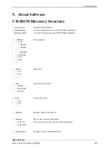
Page 42: ...dmeu html Version information on each API TOOL English APIPAC Each installer AIO DISK1 DISK2 DISKN AioWdm CNT DIO HELP HELP file Aio Cnt INF Each INF file for OS WDM Win2000 Win95 linux Linux driver file cnt dio Readme Readme file for each driver Release Driver file on each API TOOL API_NT For creation of a user specific install program API_W95 UsersGuide Hardware User s Guide PDF files ...

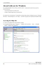
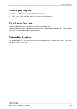
Page 43: ...s Hardware digital input output of specified bits For details refer to the help file The help file provides various items of information such as Function Reference Sample Programs and FAQs Use them for program development and troubleshooting Accessing the Help File 1 Click on the Start button on the Windows taskbar 2 From the Start Menu select Programs CONTEC API PAC W32 Dio API DIO HELP to displa...

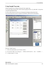
Page 44: ...mber set by API TOOL Configuration in the DrvNo and GrpNo fields Use these sample programs as references for program development and operation check The sample programs are stored in Program Files CONTEC API PAC W32 Dio Samples Running a Sample Program 1 Click on the Start button on the Windows taskbar 2 From the Start Menu select Programs CONTEC API PAC W32 Dio SAMPLE 3 A sample program is invoke...

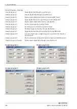
Page 45: ...ecified bit Sample program 6 Services interrupts of a specified board Sample program 7 Provides process control of a specified board Sample program 8 Performs trigger monitoring of a specified board Sample program 9 Inputs digital data through a specified port using BCD data Sample program 10 Executes digital input simple functions at specified bits through a specified port Sample program 11 Servi...

Page 46: ...ow 1 Click on the Start button on the Windows taskbar From the Start Menu select Control Panel 2 Double click on Add Remove Programs in the Control Panel 3 Select CONTEC API DIO 98 PC xx from the application list displayed then click on the Change Remove button Follow the on screen instructions to uninstall the function libraries ...

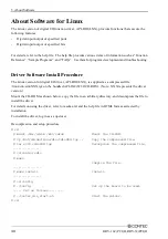
Page 47: ...s supplied as a compressed file linux dio cdioXXX tgz on the bundled API PAC W32 CD ROM Note XXX represents the driver version Mount the CD ROM as shown below copy the file to an arbitrary directory and decompress the file to install the driver For details on using the driver refer to readme txt and the help file in HTML format extracted by installation To install the driver log in as a superuser ...

Page 48: ...g Sample Programs Sample programs have been prepared for specific basic applications Sample programs for each language are contained in the contec cdio samples directory For compiling them refer to the manual for the desired language Uninstalling the driver To uninstall the driver use the uninstall shell script contained in the contec cdio directory For details check the contents of the script ...

Page 49: ...5 About Software 42 RRY 16C PCI H RRY 32 PCI H ...

Page 50: ... 20 000 000 operations min or more Switching times 180 min Electrical lifetime 100 000 operations min or more Switching times 20 min Relay Contact Spec Relay Type PCN 105D3MHZ I O Addresses 8 bits x 32 ports boundary Max board count in One System 16 boards including this board Power Consumption 5 VDC 550mA Max Operating Condition 0 50 C 10 90 RH No condensation PCI Bus Specification 32bit 33MHz Un...

Page 51: ...ct Spec Relay Type MSG 105AK1 or equivalent to it I O Address 8 bits x 32 ports boundary Max board count in One System 16 boards including this board Power Consumption 5 VDC 1050mA Max Operating Condition 0 50 C 10 90 RH No condensation PCI Bus Specification 32bit 33MHz Universal key shapes supported 1 Dimension mm 176 41 L x 105 68 H Weight 150g 1 This board requires 5V power supply from expansio...

Page 52: ... Hardware RRY 16C PCI H RRY 32 PCI H 45 Block Diagram RRY 16C PCI H RRY 16C PCI H PCI bus Control circuit Reed Relay Driver Driver Output port 0 Output port 1 Reed Relay Figure 6 1 Block Diagram RRY 16C PCI H ...

Page 53: ...I H RRY 32 PCI H RRY 32 PCI H RRY 32 PCI H PCI bus Control circuit Output port 0 Reed Relay Driver Driver Driver Driver Reed Relay Reed Relay Reed Relay Output port 1 Output port 2 Output port 3 Figure 6 2 Block Diagram RRY 32 PCI H ...

Page 54: ...specifications RRY 16C PCI H RRY 16C PCI RRY 16C PCI H I O address 8 bits x 4 ports boundary 8 bits x 32 ports boundary Power consumption 5VDC 700mA Max 5VDC 550mA Max PCI bus specification 32bit 33MHz 5V 32bit 33MHz Universal key shapes supported Supply 5V to the 5V pin Dimension mm 121 69 L x 106 68 H 121 69 L x 105 68 H RRY 32 PCI H RRY 32 PCI RRY 32 PCI H I O address 8 bits x 4 ports boundary ...

Page 55: ...ogawa ku Osaka 555 0025 Japan Japanese http www contec co jp English http www contec com Chinese http www contec com cn No part of this document may be copied or reproduced in any form by any means without prior written consent of CONTEC CO LTD 02032005 02032005 Management No A 51 008 Parts No LYES141 ...

Reviews: