background image

  Introduction 


SH-9008AT-POE Reference Manual 

-  7  - 

3.


Features 


PoE power supply function based on IEEE802.3af, 

IEEE802.3at 

Power can be supplied to PoE devices that conform to IEEE802.3af, IEEE802.3at. Up to 30W per port and up to 120W * for all ports can 
be powered. 
*There is a limit to supply the power depending on the power input voltages. 


Eight of 1000BASE-T ports are equipped   

The product has eight ports which conform to IEEE802.3ab(1000BASE-T) / IEEE802.3u(100BASE-TX)/ IEEE802.3(10BASE-T). 
Due to the fan-less design, this hub can be used in the places where the quietness or a longer lifetime of the product is desired. 
Furthermore, a metal housing with excellent heat dissipation enables the product to be operated in the temperature between -35 °C and 
+70 °C. 


Capable of operating in a wide-ranged power inputs, 

and features dual power support 

The product is capable of operating in a wide range of DC power between 12 and 57VDC. Moreover, dual power supports the product 
to continue to work even if one of the power supplies fails. Failures of the power supply can be seen with the LED on the front panel or 
the failure detection relay circuit. 


DIN rail mounting or Wall installation 

With the supplied brackets, the product can be set on a 35mm-DIN rail or on the wall. 


Summary of Contents for SH-9008AT-POE

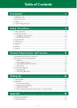
Page 1: ... CONTENTS Industrial 8 port unmanaged Gigabit PoE Ethernet Switching HUB SH 9008AT POE Introduction 4 Safety Precautions 9 Product Nomenclature and Function 16 Setting Up 24 Appendix 30 Customer Support and Inquiry 35 ...

Page 2: ...enclature and Function 16 1 Nomenclature of Product Components 17 2 Description of Product Components 18 1 LAN Port 18 2 Power Supply Connector 19 3 Power Failure Detection DIP Switch 20 4 LED Indicator 21 3 Connecting to Network 22 1 Network Cable 22 2 Connection Restrictions 23 Setting Up 24 1 Power Supplies 25 2 Installation 26 1 Mounting on a DIN rail 26 2 Removing from a DIN Rail 27 3 Setting...

Page 3: ... 3 Table of Contents Customer Support and Inquiry 35 1 Services 36 ...

Page 4: ... 4 Introduction This section provides necessary information of the product such as the outline bundled items and manuals before actual use ...

Page 5: ...t Guide Must read this after opening the package This lists the product configuration and describes the precautions Included in the package Printed matter Reference Manual This document Read this when operating the product This describes the hardware aspects such as functions and settings Download from the Contec website PDF Download Manuals Download the manuals accordingly from the following URL ...

Page 6: ... conform to IEEE802 3af and IEEE802 3at The functions including jumbo frames AutoMDI MDI X and auto negotiations are within Due to the fan less design this hub can be used in the places where the quietness or a longer lifetime of the product is desired Furthermore a metal housing with excellent heat dissipation enables the product to be operated in the temperature between 35 C and 70 C The product...

Page 7: ...used in the places where the quietness or a longer lifetime of the product is desired Furthermore a metal housing with excellent heat dissipation enables the product to be operated in the temperature between 35 C and 70 C Capable of operating in a wide ranged power inputs and features dual power support The product is capable of operating in a wide range of DC power between 12 and 57VDC Moreover d...

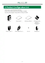
Page 8: ...items listed below Check with the following list that your package is complete If you discover damaged or missing items contact your retailer Product 1 Product Guide 1 Warranty Certificate 1 DIN Rail Mounting Bracket 1 attached to the product Power Connector 1 RJ45 Protection Cap 8 Screw 8 Wall Bracket 2 ...

Page 9: ... 9 Safety Precautions Understand the following definitions and precautions to use the product safely Never fail to read them before using the product ...

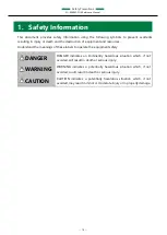
Page 10: ...rstand the meanings of these labels to operate the equipment safely DANGER DANGER indicates an imminently hazardous situation which if not avoided will result in death or serious injury WARNING WARNING indicates a potentially hazardous situation which if not avoided could result in death or serious injury CAUTION CAUTION indicates a potentially hazardous situation which if not avoided may result i...

Page 11: ...other applications that require a very high level of reliability Do not use the product in such applications If using this product in applications where safety is critical such as in railways automotive or disaster prevention or security systems please contact your retailer CAUTION Do not use or store the product in a location exposed to extremely high or low temperature or susceptible to a rapid ...

Page 12: ...ad on the connected part Doing so may result in poor contact or damage to the product and the connected part To suppress noise emission from the product set a ferrite core to the power cable and LAN cable refer to page 18 and 19 Do not touch metal parts or terminals with your hands when the product is in operation Otherwise the product may malfunction or cause failure Do not touch the product or c...

Page 13: ...and if not installed and used in accordance with the instruction manual may cause harmful interference to radio communications Operation of this equipment in a residential area is likely to cause harmful interference in which case the user will be required to correct the interference at his own expense FCC WARNING Changes or modifications not expressly approved by the party responsible for complia...

Page 14: ... human safety and may significantly affect the maintenance of public functions 2 Therefore do not use the product for such purposes 1 Medical devices such as life support equipment and devices used in an operating theater 2 Main control systems at nuclear power stations safety maintenance systems at nuclear facilities other important safety related systems operation control systems within group tr...

Page 15: ... product periodically to use it safely Check the ventilation slit and make sure that it is not blocked by dust or foreign matter 6 Storage When storing this product keep it in its original packing form Put this product in the storage bag Wrap it in the packing material and then put it in the box Store the package at room temperature at a place free from direct sunlight moisture shock vibration mag...

Page 16: ... 16 Product Nomenclature and Function This section describes product component names and their functions pin assignment of each connector ...

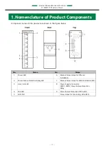
Page 17: ...n the figure below No Name No Name 1 Power LED 6 Bracket Screw Holes for DIN rail Installation 2 Power Failure Detection Relay LED 7 Bracket Screw Holes for Wall Installation M3 3 Link Act LED 8 Power Supply Connector PWR1 PWR2 Power Failure Detection Relay 4 PoE LED 9 Power Failure Detection DIP Switch 5 LAN Port Screw Holes for Grounding Wire M3 ...

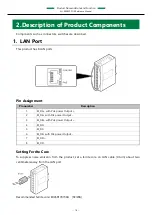
Page 18: ...AN ports Pin Assignment Pin number Description 1 BI_DA with PoE power Output 2 BI_DA with PoE power Output 3 BI_DB with PoE power Output 4 BI_DC 5 BI_DC 6 BI_DB with PoE power Output 7 BI_DD 8 BI_DD Setting Ferrite Core To suppress noise emission from the product set a ferrite core on LAN cable 0 turn about two centimeters away from the LAN port Recommended ferrite core E04SR170730A SEIWA ...

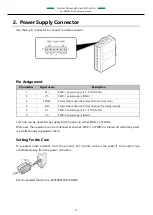
Page 19: ... Power failure detection relay terminal normally closed 5 V2 PWR 2 power supply 12 57VDC 5 6 V2 PWR 2 power supply GND This hub can be operated by supplying the power to either PWR 1 or PWR 2 Moreover the operation can be continued even when PWR 1 or PWR 2 is turned off while the power is simultaneously supplied to them Setting Ferrite Core To suppress noise emission from the product set a ferrite...

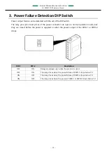
Page 20: ... are open in normal operation mode but they are closed before the power is supplied or when the power output of the PWR 1 or PWR 2 drops DIP 1 DIP 2 Description OFF ON Relays are always open when the product is used OFF ON The relay closes when the power failure of PWR 1 drops below 7V ON OFF The relay closes when the power failure of PWR 2 drops below 7V ON OFF The relay closes when the power of ...

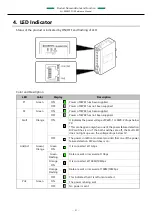
Page 21: ... of PWR 1 or PWR 2 drops below 7V This can happen only when one of the power failure detection DIP switches is on If the both switches are off the Fault LED does not light up even the voltage drops below 7V OFF The power condition is normal provided that one of the power failure detection DIP switches is on Link Act Green Orange Green ON It is connected at 1Gbps Green Flashing Data are sent or rec...

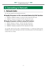
Page 22: ... T Category 5e or greater UTP STP cable within 100 meters Supply the power without using PoE function 10BASE T Category 3 or greater UTP STP cable within 100 meters 100BASE TX Category 5 or greater UTP STP cable within 100 meters 1000BASE T Category 5e or greater UTP STP cable within 100 meters UTP and STP cables have two types a straight through type or a crossed type With the Auto MDI MDI X func...

Page 23: ...BASE TX Class II repeaters is possible In addition the total maximum cable length of cables 1 2 3 is 205m or less For details see the operation manual of your 100BASE TX repeater HUB Connection Restrictions with 10BASE T Repeater HUBs As many as four stages of 10BASE T repeater HUBs can be connected using cascade connection In addition the maximum length of UTP and STP cables between cascaded HUBs...

Page 24: ... 24 Setting Up This section describes how to set up the product ...

Page 25: ...power specification required The hub can be operated by supplying the power to either PWR 1 or PWR 2 Moreover the operation can be continued even when PWR 1 or PWR 2 is turned off while the power is simultaneously supplied to them Refer to the Power Supply Connector Page 19 for 3 pin or 4 pin operation Pin number Signal name Description 1 V1 PWR1 12 57VDC 5 2 V1 PWR1 GND 3 RRY1 Power failure detec...

Page 26: ...t with flat head M3 screws The appropriate tightening torque for the screw is less than 5kgf٠cm The bracket is preset on the product upon shipment 2 Hang the product on the upper part of the DIN rail Engage the wires attached to the bracket onto upper part of the DIN rail and press the product down to the lower side of the DIN rail Wires ...

Page 27: ... Setting Up SH 9008AT POE Reference Manual 27 2 Removing from a DIN Rail 1 While pressing the product downward lift it up from the lower part of the DIN rail ...

Page 28: ...Wall 1 Secure the wall brackets on the product with round screws M3 The appropriate tightening torque for the screw is less than 5kgf٠cm 2 Set the wall brackets on the wall with screws Use the M3 size screws Screws for the wall installations are separately required ...

Page 29: ...any surrounding objects DIN rail mounted Secure a distance of at least 50mm between the top bottom of the main product and any surrounding objects and also a distance of at least 50mm between each side of the product and any surrounding objects 5 8mm for the product overview level side ...

Page 30: ... 30 Appendix This section lists the specifications and the physical dimensions of the product and the details of model name ...

Page 31: ...Kbyte Aging time 300 seconds LED indicator POWER x 2 Green PWR Failure Orange LINK ACT x 8 Green Orange PoE x 8 Green DIP switch Power failure detection function switch for PWR 1 and PWR 2 Power supply voltage 12V 57VDC 5 FG pin Power supply connector equipped with FG pin Power consumption Max When PoE is not in use 12V 0 47A 24V 0 24A 57V 0 10A When PoE is in use 12V 7 56A 24V 7 22A 57V 3 04A Phy...

Page 32: ...000 4 4Level 3 IEC61000 4 4Level 3 Static electricity resistance Contact discharge 4KV EN61000 4 2Level 2 IEC61000 4 2Level 2 Atmospheric discharge 8KV EN61000 4 2Level 3 IEC61000 4 2Level 3 Vibration resistance Sweep resistance 10 57Hz semi amplitude 0 075mm 57 150Hz 9 8M s2 1G 40minutes each in X Y and Z directions JIS C60068 2 6 compliant IEC60068 2 6 compliant Shock resistance 10G half sine sh...

Page 33: ... Appendix SH 9008AT POE Reference Manual 33 2 Physical Dimensions When the product is mounted on DIN rail ...

Page 34: ... Appendix SH 9008AT POE Reference Manual 34 When the product is set on the wall ...

Page 35: ... 35 Customer Support and Inquiry CONTEC provides the following support services for you to use CONTEC products more efficiently and comfortably ...

Page 36: ...useful information including product manuals that can be downloaded through the CONTEC website Download https www contec com download You can download updated driver software firmware and differential manuals in several languages Membership registration myCONTEC is required to use the services ...

Page 37: ... makes no commitment to update or keep current the information contained in this document The information in this document is subject to change without notice All relevant issues have been considered in the preparation of this document Should you notice an omission or any questionable item in this document please feel free to notify your retailer Regardless of the foregoing statement CONTEC assume...

Page 38: ... ku Osaka 555 0025 Japan https www contec com No part of this document may be copied or reproduced in any form by any means without prior written consent of CONTEC CO LTD SH 9008AT POE Reference Manual NA07245 LYXZ541 06222020 June 2020 Edition ...

Reviews: