Summary of Contents for SPT-100A-22TP01

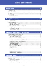
Page 1: ...emory integrated type SPT 100A 22TP01 STAND PC 21 5 inch model 8GB memory integrated type SPT 100A 22TP02 Introduction 5 Safety Precautions 11 Product Nomenclature and Function 18 Hardware Setup 31 BI...

Page 2: ...nents 22 1 LED POWER ACCESS STATUS 22 2 DC power connector DC IN Display section 22 3 USB USB for the touch screen Display section 23 4 DVI Interface DVI D Display section 24 5 Analog RGB connector VG...

Page 3: ...nfiguration 53 6 SATA Configuration 54 7 CSM Configuration 55 5 Chipset 56 1 North Bridge 57 2 Intel IGD Configuration 58 3 LCD Control 59 4 South Bridge 60 5 Azalia HD Audio Configuration 61 6 USB Co...

Page 4: ...4 Table of Contents 2 Dispose of the Battery 90 7 Life of CFast 92 Customer Support and Inquiry 93 1 Services 94...

Page 5: ...5 Introduction This section provides necessary information of the product such as the outline bundled items and manuals before actual use...

Page 6: ...w to get Product Guide Must read this after opening the package This lists the product configuration and describes the precautions Included in the package Printed matter Reference Manual Read this whe...

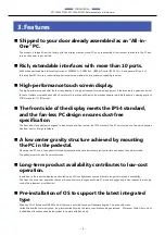
Page 7: ...tegrated high performance touch screen 21 5 inch size of the display monitor is pre installed and more than 10 ports of rich extendable interfaces such as DVI I 1000BASE T USB 3 0 serial and Audio are...

Page 8: ...ess PC design ensures dust free specification The front side of the display is designed to be dust and drip free to meet the IP 54 standard The PC unit contains no fan which ensures free from dust or...

Page 9: ...Introduction SPT 100A22TP01 SPT 100A22TP02 Reference Manual Hardware 9 4 Supported OS Windows 10 IoT Enterprise LTSB 2016 64 bit Japanese English Chinese Korean...

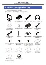
Page 10: ...1 DVI Analog RGB Conversion Adapter 1 Stand Wiring Cover 1 AC Adapter for Display 1 AC Power Cable for Display 1 USB Cable for Touch Screen 1 1 Cable Tie 2 Serial Number Label 1 USB removal preventio...

Page 11: ...11 Safety Precautions Understand the following definitions and precautions to use the product safely Never fail to read them before using the product...

Page 12: ...ources Understand the meanings of these labels to operate the equipment safely DANGER DANGER indicates an imminently hazardous situation which if not avoided will result in death or serious injury WAR...

Page 13: ...nge of specification or susceptible to rapid temperature changes e g Exposure to direct sun In the vicinity of a heat source Do not use this product in extremely humid or dusty locations It is extreme...

Page 14: ...rs to perform operations on the touch screen Operations with the stylus pen on the screen might not perform well due to the pen you are using with LCD may have a few bright spots that are always on or...

Page 15: ...and can radiate radio frequency energy and if not installed and used in accordance with the instruction manual may cause harmful interference to radio communications Operation of this equipment in a...

Page 16: ...or accumulators at their end of life should be disposed separately from the household waste If a chemical symbol is printed beneath the symbol mark shown above it indicates that the battery or accumu...

Page 17: ...performs unintended operations 2 Security measures e g Do not keep using the default password Refer to the product manual for the password setting Set a strong password Combined with upper and lowerca...

Page 18: ...18 Product Nomenclature and Function This section describes product component names and their functions pin assignment of each connector...

Page 19: ...19 1 Nomenclature of Product Components Component names of the product are shown in the figure below Product front view Display section rear view Display section bottom view Touch screen display Disp...

Page 20: ...x 1 DVI D Display port 24 pin Female VGA Display port 15 pin HD SUB Female PC section connector POWER LED PC power ON display LED STATUS LED Status LED ACCESS LED CFast disk access display LED DC IN...

Page 21: ...3 LAN A Ethernet 1000BASE T 100BASE TX 10BASE T RJ 45 connector LAN B Ethernet 1000BASE T 100BASE TX 10BASE T RJ 45 connector CFast1 CFast card slot SATA connection CFast2 CFast card slot SATA connec...

Page 22: ...STATUS LED Off You can control the behavior of LED from the user application 1 ON Red You can control the behavior of LED from the user application 1 POWER LED Display Off Power of the display sectio...

Page 23: ...roduct has a USB connector TYPE B for the touch screen Use the bundled cable to connect to the USB connector on the PC One side of the USB cable for the touch screen is already connected to the displa...

Page 24: ...DVI cable for the display is already connected to the display section upon shipping Connect the other end of the cable to the PC DVI Connector Connector used on the display DVI D connector 24 pin Fem...

Page 25: ...g RGB connector Connector used on the display 15 pin HD SUB Female Pin number Signal name Pin number Signal name 1 DCD 9 5V 2 RD 10 GND 3 TD 11 N C 4 DTR 12 DDCDATA 5 GND 13 HSYNC 6 DSR 14 VSYNC 7 RTS...

Page 26: ...is product has a connector for DVI I connections Use the bundled cable to connect to the DVI D interface on the display section The connector name is DVI DVI I 29 pin DVI Connector Connector used on t...

Page 27: ...0 This product has 1 port for USB 3 0 TYPE A interface USB3 0 Connector Pin No Signal Name 1 USB_VCC 2 DATA 3 DATA 4 GND 5 SSRX 6 SSRX 7 GND 8 SSTX 9 SSTX 12 USB2 0 port USB2 0 This product has 5 por...

Page 28: ...th 100m segment Controller Intel Ethernet Connection I210IT Operation at 1000Mbps requires a category 5E cable or above Giga bit Ethernet Connector Pin No Signal Name 100BASE TX 1000BASE T 1 TX TRD 0...

Page 29: ...name Pin number Signal name Pin number Signal name PC1 CDI PC11 N C S1 GND PC2 GND PC12 N C S2 TX PC3 N C PC13 3 3V S3 TX PC4 N C PC14 3 3V S4 GND PC5 N C PC15 GND S5 RX PC6 N C PC16 GND S6 RX PC7 GND...

Page 30: ...e an I O address interrupt and unused state for each of the ports independently The same I O address and IRQ cannot be shared with any other device SERIAL I O Address and Interrupt SERIAL I O address...

Page 31: ...31 Hardware Setup This section describes how to install connect and set up the product...

Page 32: ...te cables STEP3 Turn on the power After verifying that you have correctly followed steps 1 and 2 turn on the power If you find any abnormality after turning on the power turn it off and check to see i...

Page 33: ...p Before you start be sure that the power is turned off 1 How to remove the display 1 Turn off the power of the product 2 Unplug the USB cable for touch screen and the DVI cable for display from the p...

Page 34: ...isplay 1 Slide down the display along the stand to set into place 2 Secure the display with screws The position of USB cable for touch screen To meet the standard specification connect the USB cable f...

Page 35: ...steps described in How to remove the display page xxx to remove the display 2 Unscrew 4 screws from VESA plate that is fixed to the back of the display 3 As illustrated below turn the display vertica...

Page 36: ...ference Manual Hardware 36 5 Secure the display with screws To set the PC with the display installed vertically When using the display vertically right click on Windows screen and go to Property Selec...

Page 37: ...display use the buttons on the back side of the display as shown below Display setting menu Screen Description CONTRAST This adjusts the contrast of the screen BRIGHTNESS This adjusts the brightness...

Page 38: ...etting screen OSD DOWN UP This adjusts the position of the setting screen OSD TIMEOUT This adjusts the length of time to display the setting screen FACTORY RESET This restores the factory settings DVI...

Page 39: ...SPT 100A22TP02 Reference Manual Hardware 39 5 Calibration setting Follow the steps described below to perform calibration 1 Open the Control Panel in Windows system tool 2 Open the Hardware and Sound...

Page 40: ...PT 100A22TP02 Reference Manual Hardware 40 4 From Display tab open the Calibrate in the Display options 5 Follow the instruction shown on the display and tap the screen 6 When calibration has complete...

Page 41: ...2TP02 Reference Manual Hardware 41 6 Installation Requirements When using the product with the supplied cables do not tilt the display monitor more than 45 degrees Installation Image the display monit...

Page 42: ...42 BIOS Setup This chapter describes American Megatrends AMI Setup program that is built into the FLASH ROM BIOS...

Page 43: ...system information contained in the CMOS ROM and begins the process of checking out the system and configuring it When it finishes the BIOS will seek an operating system on one of the disks and then l...

Page 44: ...indows 7 defaults from BIOS default table Do not use this F4 Save all settings changes to the FLASH ROM and exit F5 Load Windows 10 defaults from BIOS default table 3 Getting Help Press F1 to pop up a...

Page 45: ...00 05 00 00 TXE FW Version 01 01 00 1089 System Language English System Date Week Day MM DD YYYY System Time HH MM SS Access Level Administrator Select Screen Select Item Enter Select Change Opt F1 Ge...

Page 46: ...pliancy UEFI 2 4 PI 1 3 Displays the UEFI version Project Version B956C x xx x64 This item displays the BIOS version Build Data and Time xx xx xxxx xx xx xx This item displays the BIOS creation date a...

Page 47: ...eral Help F2 Previous Values F3 Load Defaults for Win7 F4 Save Exit F5 Load Defaults for Win10 ESC Exit Version x xx xxxx Copyright C 20xx American Megatrends Inc ACPI Settings Use this menu to config...

Page 48: ...Hibernation settings ACPI Sleep State Suspend Disabled S3 Suspend to RAM Configure the Sleep State settings Wake on LAN RI Control on S5 Disabled Enabled Configure the Wake on LAN settings and Resume...

Page 49: ...Port A Configuration Refer to Serial Port A Configuration Serial Port B Configuration Refer to Serial Port B Configuration Digital I O Configuration Refer to Digital I O Configuration Serial Port A C...

Page 50: ...GPIO 0 GPIO 1 GPIO 2 GPIO 3 GPIO 4 GPIO 5 Input Output High Output Low Configure the operation settings for Digital I O input output And configure the operation settings for output level High Low Inp...

Page 51: ...Pc Health Status System temperature 35 C CPU temperature 42 C VCORE 0 888 V 1 8V 1 760 V 5 V 5 024 V 12 V 12 032 V 3 3 VSB 3 312 V 3 3 VCC 3 296 V VBAT 3 216 V Select Screen Select Item Enter Select...

Page 52: ...pported Execute Disable Bit Enabled Intel Virtualization Technology Disabled Select Screen Select Item Enter Select Change Opt F1 General Help F2 Previous Values F3 Load Defaults for Win7 F4 Save Exit...

Page 53: ...eport Disabled S0ix Disabled Select Screen Select Item Enter Select Change Opt F1 General Help F2 Previous Values F3 Load Defaults for Win7 F4 Save Exit F5 Load Defaults for Win10 ESC Exit Version x x...

Page 54: ...it Version x xx xxxx Copyright C 20xx American Megatrends Inc SATA Configuration Item Options Description Serial ATA SATA Enabled Disabled Configure the SATA controller operation settings Changing thi...

Page 55: ...ption ROM execution Storage UEFI Video Legacy Other PCI devices UEFI Select Screen Select Item Enter Select Change Opt F1 General Help F2 Previous Values F3 Load Defaults for Win7 F4 Save Exit F5 Load...

Page 56: ...Save Exit North Bridge South Bridge Select Screen Select Item Enter Select Change Opt F1 General Help F2 Previous Values F3 Load Defaults for Win7 F4 Save Exit F5 Load Defaults for Win10 ESC Exit Ver...

Page 57: ...x TOLUD 3 GB Bypass SPD Detect Disable Select Screen Select Item Enter Select Change Opt F1 General Help F2 Previous Values F3 Load Defaults for Win7 F4 Save Exit F5 Load Defaults for Win10 ESC Exit V...

Page 58: ...ct Item Enter Select Change Opt F1 General Help F2 Previous Values F3 Load Defaults for Win7 F4 Save Exit F5 Load Defaults for Win10 ESC Exit Version x xx xxxx Copyright C 20xx American Megatrends Inc...

Page 59: ...Load Defaults for Win10 ESC Exit Version x xx xxxx Copyright C 20xx American Megatrends Inc LCD Control Item Options Description Primary IGFX Boot Display CRT DVI LFP Configure the settings for the po...

Page 60: ...Bridge Item Options Description Azalia HD Audio Refer to Azalia HD Audio Configuration USB Configuration Refer to USB Configuration LAN Configuration Refer to LAN Configuration High Precision Timer E...

Page 61: ...Chipset Audio Configuration Audio Controller Enabled Select Screen Select Item Enter Select Change Opt F1 General Help F2 Previous Values F3 Load Defaults for Win7 F4 Save Exit F5 Load Defaults for W...

Page 62: ...ends Inc USB Configuration Item Options Description Legacy USB Support Enabled Disabled Auto Configure whether USB keyboards and similar devices will be usable with legacy operating systems such as MS...

Page 63: ...E UEFI Select Screen Select Item Enter Select Change Opt F1 General Help F2 Previous Values F3 Load Defaults for Win7 F4 Save Exit F5 Load Defaults for Win10 ESC Exit Version x xx xxxx Copyright C 20x...

Page 64: ...um length 20 Administrator Password User Password Secure Boot menu Select Screen Select Item Enter Select Change Opt F1 General Help F2 Previous Values F3 Optimized Defaults F4 Save Exit ESC Exit Vers...

Page 65: ...dware 65 Secure Boot menu This is viewed when Windows 10 Load Defaults is performed Leave these settings as configured before shipment CAUTION Be careful to not forget the password If you forget the p...

Page 66: ...de Setup Secure Boot Not Active Vendor Keys Not Active Secure Boot Enabled Secure Boot Mode Standard Key Management Select Screen Select Item Enter Select Change Opt F1 General Help F2 Previous Values...

Page 67: ...Exit F5 Load Defaults for Win10 ESC Exit Version x xx xxxx Copyright C 20xx American Megatrends Inc Boot Configuration Item Options Description Setup Prompt Timeout 1 Set the standby time for BIOS Set...

Page 68: ...USB Disk 2 UEFI USB Disk In such cases if 1 is selected a legacy boot is performed under the assumption the disk is MBR formatted If 2 is selected a UEFI boot is performed under the assumption the di...

Page 69: ...th ME disable ModeMEUD000 Select Screen Select Item Enter Select Change Opt F1 General Help F2 Previous Values F3 Load Defaults for Win7 F4 Save Exit F5 Load Defaults for Win10 ESC Exit Version x xx x...

Page 70: ...ardware 70 Restore User Defaults Return the settings to the user default values Boot Override Configure the settings for temporary booting from a connected device other than that set in Boot Configura...

Page 71: ...71 Appendix This section lists the specifications and the physical dimensions of the product and the details of model name...

Page 72: ...0 Point multi touch Touch screen communication method USB Aspect ratio 16 9 Pixel pitch 0 247 x 0 247 mm Resolution max Display color max 1 920 x 1 080 60Hz 16 770 000 colors Contrast ratio max 1 000...

Page 73: ...capacity CFast card slot 3 3V 1A 500mA 2 USB3 0 I F 5V 0 9A 900mA 1 USB2 0 I F 5V 2 5A 500mA 5 Physical dimensions mm Display horizontal installation 517 W x 270 D x 391 H No protrusions Display verti...

Page 74: ...e 1KV EN61000 4 4 Level3 IEC61000 4 4 Level3 Static electricity resistance Contact discharge 4kV IEC61000 4 2 Level 2 EN61000 4 2 Level 2 Atmospheric discharge 8kV EN61000 4 2 Level 3 IEC61000 4 2 Lev...

Page 75: ...vertical installation When installing the display vertically connecting cables need to be acquired individually Recommended cables Name Model Maker DVI cable 1m DLD2 1M TL THIRDWAVE Corporation USB ca...

Page 76: ...Appendix SPT 100A22TP01 SPT 100A22TP02 Reference Manual Hardware 76 Set the display bracket in the center 270 505 313 230 10 2 mm...

Page 77: ...th Bridge initialization Specific North Bridge 19h PRI memory South Bridge initialization starts 1Ah 1Ch PRI memory South Bridge initialization Specific South Bridge 1Dh 2Ah OEM PRI memory initializat...

Page 78: ...Bridge DXE initialization starts 71h South Bridge DXE SMM initialization starts 72h South Bridge device initialization 73h 77h South Bridge DXE initialization Specific South Bridge module 78h ACPI mod...

Page 79: ...ROM initialization B3h System reset B4h USB hotplug B5h PCI bus hot plug B6h NVRAM cleanup B7h Configuration reset Reset the NVRAM settings B8h BFh For future AMI codes reserved C0h CFh OEM BDS initia...

Page 80: ...r register RBR 1 W Divisor latch register LSB DLL 03F9H 1 W Divisor latch register MSB DLM 0 W Interrupt enable register IER 03FAH X R Interrupt ID register IIR 03FBH X W Line control register LCR 03F...

Page 81: ...Appendix SPT 100A22TP01 SPT 100A22TP02 Reference Manual Hardware 81 I O address Description 03F9H 03FAH...

Page 82: ...Appendix SPT 100A22TP01 SPT 100A22TP02 Reference Manual Hardware 82 I O address Description 03FBH 03FCH...

Page 83: ...SPT 100A22TP02 Reference Manual Hardware 83 I O address Description 03FDH 03FEH 03FFH SCR Scratchpad Register This is an 8 bit readable writable register which is available to the user to allow data...

Page 84: ...typical baud rates and their respective values to be written to the divisor latch register LSB MSB Baud Rate Settings Baud rate to be set SERIAL A B Clock input 1 8432MHz Value to be set in the diviso...

Page 85: ...ftware can be configured using 255 levels 1 to 255 seconds of timeout intervals for the watchdog timer There is also a 2 second tolerance for timeout intervals To maintain normal system operation trig...

Page 86: ...en in Intel8086 assembly language WDT Initial Enter the extended function mode MOV DX 2EH MOV AL 87H OUT DX AL OUT DX AL Select logical device WDT number 8 MOV DX 2EH MOV AL 07H OUT DX AL MOV DX 2FH M...

Page 87: ...AL MOV DX 2FH MOV AL 00H OUT DX AL Exit the extended function mode MOV DX 2EH MOV AL AAH OUT DX AL WDT START counter set and a start Enter the extended function mode MOV DX 2EH MOV AL 87H OUT DX AL OU...

Page 88: ...V DX 2FH The data of an example is 15 seconds 01H 1sec FFH 255sec MOV AL 0FH 0FH 15Sec OUT DX AL Exit the extended function mode MOV DX 2EH MOV AL AAH OUT DX AL WDT STOP Enter the extended function mo...

Page 89: ...al Hardware 89 Stop count down of WDT MOV DX 2EH MOV AL F1H OUT DX AL MOV DX 2FH The data of 00H is stop WDT MOV AL 00H OUT DX AL Exit the extended function mode MOV DX 2EH MOV AL AAH OUT DX AL CAUTIO...

Page 90: ...ary battery Model BR 1 2AA Maker Panasonic Nominal Voltage 3V Nominal capacity 550mAh Lithium content 1g or less 2 Dispose of the Battery CAUTION When disposing of a used battery follow the disposal p...

Page 91: ...Appendix SPT 100A22TP01 SPT 100A22TP02 Reference Manual Hardware 91 2 Removing the screws allows you to detach the PC 3 Remove the screws from the PC cover and then remove the main unit cover...

Page 92: ...endurance days Total capacity KB Management page size KB NAND Flash memory life span cycles The number of management page to be rewritten per 1 cycle Example Q MLC When the file of 4MB is made for CF...

Page 93: ...93 Customer Support and Inquiry CONTEC provides the following support services for you to use CONTEC products more efficiently and comfortably...

Page 94: ...offers the useful information including product manuals that can be downloaded through the CONTEC website Download https www contec com download You can download updated driver software firmware and...

Page 95: ...ment is subject to change without notice All relevant issues have been considered in the preparation of this document Should you notice an omission or any questionable item in this document please fee...

Page 96: ...apan https www contec com No part of this document may be copied or reproduced in any form by any means without prior written consent of CONTEC CO LTD SPT 100A22TP01 SPT 100A22TP02 Reference Manual Ha...

Reviews: