background image

Chapter

 Hardware setup 


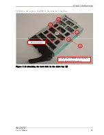
(3) After remove four screws, the bracket for the extension board. 


The four screws 

Figure 3.3 Removing the extension board bracket 


18


User’s Manual 

Summary of Contents for VPC-2000

Page 1: ...FA PC VPC Series VPC 2000 User s Manual CONTEC CO LTD...

Page 2: ......

Page 3: ...ication 14 CHAPTER HARDWARE SETUP 15 Before Using the VPC 2000 for the First Time 15 Hardware setup 16 Removing the top cover and drive bay 16 Locations and settings of internal connectors and jumpers...

Page 4: ...the power on AT power operation by the AC power supply turning on 53 Factory default setting 54 MAIN 55 Advanced 55 Boot 59 Security 60 Chipset 60 Exit 62 CHAPTER EACH COMPONENT FUNCTION 63 Component...

Page 5: ...Starting the setup screen 107 Main Window 108 Create RAID drive Mirroring 109 Delete RAID drive Mirroring 111 Software RAID monitoring tool Rapid storage technology 112 Rapid storage technology Insta...

Page 6: ...status 125 Hardware RAID setup 126 Operation flow 126 For the error 128 RAID setup when replacing the HDD 129 Hot swap 130 OS recovery setting 131 FAQ Troubleshooting 132 FAQ 132 Troubleshooting 133...

Page 7: ...sional Japanese VPC 2000 37225B Intel Core i5 660 VPC 2000 47225B Intel Core i7 860 Memory 2GB SATA 160GB DVD Multi drive Windows 7 Professional Japanese Basic performance Intel Core i7 is installed C...

Page 8: ...nal ENU JPN CHS 7 PC3 10600 DDR3 4GB 2GB 2 D Windows 7 Professional ENU VGA Keyboard 0 None 0 None 1 AD 8001 AMD M72 1 Japanese 109 keyboard PS 2 A English 104 keyboard PS 2 Hard disk SATA1 0 None Mou...

Page 9: ...arranty CONTEC products are warranted by CONTEC CO LTD to be free from defects in material and workmanship for up to one year from the date of purchase by the original purchaser Repair will be free of...

Page 10: ...ced usage misuse or malfunction of this device Safety precaution Understand the following definitions and precautions to use the product safely Safety infomation This document provides safety informat...

Page 11: ...t before plugging or unplugging a extension board or any connector CONTEC reserves the right to refuse to service a product modified by the user In the event of failure or abnormality foul smells or e...

Page 12: ...of the standard of this product becomes only a main body Copyright No part of this document may be copied or reproduced in any form by any means without prior written consent of CONTEC CO LTD CONTEC C...

Page 13: ...O Front LED output x2 Rear output x2 Input x4 Software API support User application RAS function WDT sec 255sec Resetting operation by end Remote reset Remote power on External input signal Software R...

Page 14: ...compliant IEC68 2 27 compliant Standard RoHS EMC EN55022 EN61000 6 2 and LVD EN60950 1 Do not use under environmental conditions beyond normal specifications The system may malfunction Option Mirror c...

Page 15: ...Chapter About the product Physical dimensions VPC 2000 mm Figure 2 1 VPC 2000 User s Manual 9...

Page 16: ...hapter About the product At installation the wall mount stand of VPC 2000 horizontal installation mm Figure 2 2 At installation the wall mount stand of VPC 2000 horizontal installation 10 User s Manua...

Page 17: ...Chapter About the product At installation the wall mount stand of VPC 2000 Vertical installation mm Figure 2 3 At installation the wall mount stand of VPC 2000 Vertical installation User s Manual 11...

Page 18: ...Chapter About the product Motherboard Block chart Figure 2 4 Motherboard Block chart 12 User s Manual...

Page 19: ...tch Membrane switch Connector USB PS 2 Conversion connector attachment Length of cable mm 1500mm 1700mm It becomes optional of VPC 2000 in the keyboard Please inquire details like the specification et...

Page 20: ...of wheels 1 Piece Length of cable 1830mm 1850mm Physical specification Physical dimensions H x D x W 39 5mm x 117mm x 62 1mm Tracking Resolution 460dpi Environment specification Dustproof Waterproof D...

Page 21: ...cables STEP3 Tuen on the Power After venifying that you have correctly steps 1 and 2 turn on the power If you find any abnormality after turning on the power turn it off and check to see if the setup...

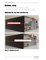
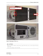
Page 22: ...that physical jolts are avoided Remove only those screws that are explained Do not move any other screw Removing the top cover and drive bay 1 Remove the top cover Figure 3 1 Removing the top cover S...

Page 23: ...ver Push on the latch and remove the front front horizontally Figure 3 2 Opening the front cover When you install remove a front bezel take sufficient care to avoid contact with the front LED Contact...

Page 24: ...Chapter Hardware setup 3 After remove four screws the bracket for the extension board The four screws Figure 3 3 Removing the extension board bracket 18 User s Manual...

Page 25: ...jumpers Once you have removed the case cover the bracket for the extension board and the drive bay unit you will be able to see the connectors and jumpers as illustrated below Figure 3 4 Locations and...

Page 26: ...ion Reference page FPAUD1 2 EXT_SMBUS1 2 SPDIF1 2 DIO_CN1 Degital I O connector P26 72 USB910 USB9 10 connector P27 70 USB56 USB5 6 connector P27 70 XBT2 Battery connector XBT3 5V dual voltage connect...

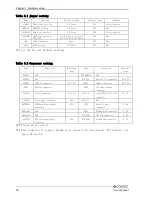
Page 27: ...setting JCMOS1 Function State usually Factory default setting CMOS clear Always set CMOS Clear with the AC cable unplugged and before reconnecting the power restore it to its normal setting Clearing...

Page 28: ...try this setting Please set the CMOS again when the system starts Table 3 5 ROM clear setting JROMCLR1 Function State usually Factory default setting ROM clear COM3 port setting JSETCOM3 JRS4 JSETCOM3...

Page 29: ...Chapter Hardware setup COM3 RS 232C 485 terminator JRS3 Table 3 7 COM3 terminator setting JRS3 JRS3 None State usually Factory default setting It is CTS It is RTS It is RXD It is TXD User s Manual 23...

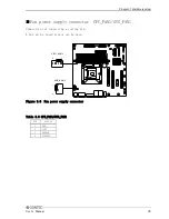
Page 30: ...gure 3 5 ATX power supply connector Table 3 7 EATXPWR1 PIN SIGNAL PIN SIGNAL 1 3 3V 13 3 3V 2 3 3V 14 12V 3 GND 15 GND 4 5V 16 PS_ON 5 GND 17 GND 6 5V 18 GND 7 GND 19 GND 8 PW_OK 20 NC 9 5V_SB 21 5V 1...

Page 31: ...r CPU_FAN1 SYS_FAN1 Connectors for connecting a cooling fan A fan with a speed sensor can be used CPU_FAN1 4 1 SYS_FAN1 1 4 Figure 3 6 Fan power supply connector Table 3 9 CPU_FAN1 SYS_FAN1 PIN SIGNAL...

Page 32: ...rear of the main unit For details refer to Chapter 5 Functions of Each Unit Digital I O Interface 2 16 1 15 Figure 3 7 Digital I O connector Table 3 10 DIO_CN1 PIN SIGNAL PIN SIGNAL 1 5V 9 I3 2 12V 10...

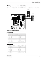
Page 33: ...acket For the VPC 2000 series the bracket is already connected to the USB connector on the front panel by a special cable USB5 6 1 2 9 10 1 2 9 10 USB9 10 Figure 3 8 Internal USB Connector Table 3 11...

Page 34: ...the front of the case For the VPC 2000 series they are already connected on the front by a special cable 2 1 POWER LED ER SW HDD LED T SW 9 10 POW RESE Figure 3 9 Internal front panel connector Table...

Page 35: ...r of the main unit COM3 1 2 9 10 1 2 9 10 COM4 Figure 3 10 COM port connector Table 3 13 COM3 RS 232C PIN SIGNAL PIN SIGNAL 1 DCD 6 CTS 2 DSR 7 DTR 3 SIN 8 RI 4 RTS 9 GND 5 SOUT 10 Key No Pin Table 3...

Page 36: ...ardware setup Attaching the hard disk 1 Remove the removable case from the drive bay The knob is pulled forward while removing the lock Lock Figure 3 11 Expanding and replaying the hard disk 1 30 User...

Page 37: ...are setup 2 Remove and replace the HDD in the removed 5 inch bay The four screws Four places of HDD in the bottom are stopped with the screw Figure 3 12 Attaching the hard disk in the drive bay 2 User...

Page 38: ...t The replacement HDD must be an S ATA drive Note the specification Push it in firmly until it connects to the connector at the back If the Removable is upper and lower opposite it cannot be connected...

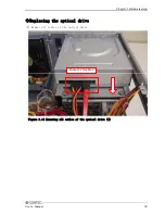
Page 39: ...Chapter Hardware setup Replacing the optical drive 1 Remove all cables of the optical drive Remove all cables Figure 3 14 Removing all cables of the optical drive 1 User s Manual 33...

Page 40: ...It moves to horizontal direction and it detaches it to the vertical direction Figure 3 15 Removing the bracket for the optical drive 3 Remove four screws and remove the optical drive Figure 3 16 Remo...

Page 41: ...xpansion memory into the memory slot For DIMM A and DIMM B use memory compliant with the specification DIMM B1 DIMM B2 DIMM A1 DIMM A2 Figure 3 17 Attaching the expansion memory 2 Lock the memory into...

Page 42: ...the extension board securely as far as it will go Figure 3 20 Attaching the expansion board Please install it very carefully might interface with the bend of various cables in the case when you instal...

Page 43: ...Chapter Hardware setup Replacing the front fan unit 1 Unscrew and remove the front fan unit Figure 3 21 Removing the front fan The two screws User s Manual 37...

Page 44: ...er 1 After push the fan braket hole remove the dustproof filter Push Figure 3 22 Replacing the dustproof filter 2 Reverse the removal procedure and re insert it During attaching the dustproof filter e...

Page 45: ...CMOS battery Figure 3 23 Removing the CMOS battery 2 The exchanged CMOS battery is prepared and attached Confirm the positive and negative poler and insert the battery Figure 3 24 Replacing the CMOS b...

Page 46: ...g the horizontal installation bracket After attaching the stand horizontal installation brackets are secured to the chassis During attaching horizontal installation brackets ensure that the upper and...

Page 47: ...Chapter Hardware setup FG connection 1 Remove the screw 2 Connect the FG cable with the removed screw The screw User s Manual 41...

Page 48: ...use of the VPC 2000 series maintain the following conditions Installable directions Please do not use by the following installations and do not set it up in other directions Vertical installation Figu...

Page 49: ...nce described in the following between the front rear and surrounding equipment walls etc Note that in the installation location air must be able to circulate Please adjust the flow of air so as not t...

Page 50: ...pins 1 Removing the DIO cover screws Remove the two screws anchoring the chassis to the DIO cover and remove the DIO cover Figure 3 28 Removing the DIO cover 2 Attaching the DIO pin cover Reverse the...

Page 51: ...and such connected to the mirror card Figure 3 29 Removing all cables Starting from the left the Serial ATA cables from the upper HDD lower HDD motherboard and power supply During connection ensure t...

Page 52: ...mirror card The four screws Figure 3 30 Removing four screws anchoring the mirror card 3 Remove the mirror card Figure 3 31 Removing the mirror card 4 Assembly is the reverse of removal During attachi...

Page 53: ...ctioning normally the Press DEL to enter SETUP screen appears Then press the DEL key After a few seconds a setup utility can be started AMI BIOS C 2006 American Megatrends Inc SMB MQ570 LLVA BIOS Ver...

Page 54: ...Enter Move to the item you desired PgUp key Increase the numeric value or make changes PgDn key Decrease the numeric value or make changes key Increase the numeric value or make changes key Decrease...

Page 55: ...menu items and the Enter key allows you to choose among them 2 After pressing the F10 key you can save the current settings by pressing the Enter key or the Y key Setting of the date and time In orde...

Page 56: ...tection Disabled 1 It is not displayed that Supervisor Password is not set Password setting The operation of the setup utility Supervisor You can change all settings User You can refer all setting but...

Page 57: ...ired order press the Esc key and return to the Main window 8 Save setup changes with Save Changes and Exit and exit Release of setted the password Although the method for doing this is the same as set...

Page 58: ...etup changes with Save Changes and Exit and exit Selecting to the IDE device Main Advanced PCIPnP Boot Security Chipset Exit IDE Configuration Configure SATA as IDE SATA 1 Not Detection SATA 2 Not Det...

Page 59: ...ds Restore on AC Power Loss Power On Resume On Ring Disabled Resume On PCI Express LAN2 Disabled Resume On PCI Device Disabled 1 Select South Bridge Chipset Configuration menu from Chipset tab 2 Selec...

Page 60: ...u are prompted to confirm that you are restoring to initial conditions Press the Y and Enter keys 3 Save setup changes with Save Changes and Exit and exit The following section describes parameters fo...

Page 61: ...System Time System Data As the Main tab differ according to date and PC configuration the above figure is a sample Advanced CPU Configuration IDE Configuration SuperIO Configuration Hardware Health Co...

Page 62: ...Disabled Intel R Virtualization Tech Enabled Execute Disable Bit Capability Enabled Intel R HT Technology Enabled Active Processor Cores All A20M Disabled Intel R SpeedSte tm tech Enabled Intel R Tur...

Page 63: ...l Serial Port4 Addrerss CA8 Serial Port4 IRQ 10 Hardware Health Configuration Chassis Intrusion Disabled CPU Warning Temperature Disabled ACPI Shutdown Temperature Disabled System Temperature 26 78 CP...

Page 64: ...PI Configuration APIC ACPI SCI IRQ Disabled High Performance Event Timer Disabled AHCI Configuration AHCI BIOS Support Enabled AHCI Port1 Not Detected AHCI Port2 Not Detected AHCI Port3 Not Detected A...

Page 65: ...Device Configuration Trunsted Configuration TCG TPM SUPPORT No PCIPnP Clear NVRAM No Boot Boot Setting Configuration Boot Device Priority Hard Disk Drives Boot Setting Configuration Quick Boot Enable...

Page 66: ...Installed User Password Not Installed Change Supervisor Password Change User Password Boot Sector Virus Protection Disabled Chipset North Bridge Configuration South Bridge Configuration Intel AMT Con...

Page 67: ...phic Adapter PCIE PCI IGD GTT Graphic smemory size No VT mode 2MB NB PCIE Configuration PEG Force GEN1 Disabled Souoth Configuration LAN1 Controller Enabled LAN1 Option ROM Disabled Resume On LAN1 Dis...

Page 68: ...n Intel VT d Disabled ME Subsystem Configuration Boot Block HECI Message Disabled HECI Message Enabled End Of Post S5 HECI Message Enabled ME HECI Configuration ME HECI Enabled ME IDER Enabled ME KT E...

Page 69: ...00 front view Optical drive unit cover Power seitch Reset switch HDD LED User LED1 User LED2 Hardware mirroring LED USB 2 0 Optical drive unit Cooler fan suction After removing the front face POWER LE...

Page 70: ...rear view Mouse connector Keyboard connector COM2 DVI Ethernet connector USB connector COM3 COM4 USB connector Digital I O connector Printer port connector FG terminal Motherboard interface COM1 CRT...

Page 71: ...6Pin mini DIN Table 5 1 Keyboard connector 1 2 3 4 5 6 K B DATA N C GND 5V K B CLOCK N C Pin No Function 3 6 4 2 1 5 Mouse interface A connector for connecting a mouse is provided Connector name is MO...

Page 72: ...s Interrupt 3F8h IRQ4 COM1 IRQ4 3E8h IRQ3 2E8h 2F8h IRQ3 COM2 IRQ4 3E8h IRQ3 2E8h CA0h IRQ11 CA8h COM3 IRQ10 CB0h CB8h CA0h IRQ10 CA8h COM4 IRQ11 CB0h CB8h The factory default settings of the BIOS are...

Page 73: ...is provided Connector name is VGA 15PinD SUB Table 5 5 CRT connector Connector D SUB 15 Pin FEMALE 1 5 11 15 10 6 Pin No Function Pin No Function 1 RED 9 VCC_TMDS 2 GREEN 10 GND 3 BLUE 11 NC 4 NC 12...

Page 74: ...n No Function Pin No Function Pin No Function 1 TMDS 2 11 TMDS 1 3 Shield 21 TMDS 5 2 TMDS 2 12 TMDS 3 22 TMDSCLK Sheild 3 TMDS 2 4 Shield 13 TMDS 3 23 TMDSCLK 4 TMDS 4 14 5V 24 TMDSCLK 5 TMDS 4 15 GN...

Page 75: ...IRQ 7 EPP version 1 9 DMA Channel DMA3 I O address 3BC can be selected only in Modes Bi Directional DMA Channel is used only in Mode ECP Table 5 8 Printer port connector Connector D SUB 25 pin FEMALE...

Page 76: ...power on In order to turn off the power forcibly hold it down for four seconds or longer USB port Six USB interfaces are provided Table 5 9 USB connector A1 A2 A3 A4 USB0 Vcc USB0 Data USB0 Data USB0...

Page 77: ...y 5E or greater Table 5 10 Ethernet connector Connector type RJ 45 LINK ACT 10 100 1000M 8 1 Pin No Signal name Function 1 TD Transmission data 2 TD Transmission data 3 RD Receive data 4 GND Ground 5...

Page 78: ...rohibition 5 PWRON 11 COMPO 6 RST 12 COMPI I0 I3 JDIO1 Pin No 1 4 Input signal You can input Input0 Input1 Input2 and Input3 O0 O3 JDIO2 Pin No 7 10 Output signal You can output Onput0 Onput1 Onput2 a...

Page 79: ...remote power and the remote reset VPC 2000 internal VPC 2000 external Example of customer construction circuit External I O connection VPC 2000 internal equivalent circuit diagram VPC 2000 external VP...

Page 80: ...Chapter Each component function Audio interface The Audio interface is provided Table 5 12 Audio connector Bule Green Pink Pin No Signal name Blue Line In Green Line Out Pink Mic In 74 User s Manual...

Page 81: ...o Signal name Pin No Signal name 1 GND 2 RWC 3 GND 4 NC 5 Key No Pin 6 NC 7 GND 8 Index 9 GND 10 MOTA 11 GND 12 NC 13 GND 14 DSA 15 GND 16 NC 17 GND 18 FDIR 19 GND 20 STEP 21 GND 22 WDATA 23 GND 24 WG...

Page 82: ...hapter Each component function Serial ATA interface Six serial ATA port interfaces are provided Table 5 14 Serial ATA connector Pin No Signal name 1 GND 2 TX 3 TX 4 GND 5 RX 6 RX 7 GND 76 User s Manua...

Page 83: ...the recovery media the following directory doesn t exist Please download each driver and utility from our homepage for the pre install model OEM Documents Drivers Pre installed models have these inst...

Page 84: ...the LZF826IO_312R EXE in the IO Lib NT folder Set it up according to the following procedure 1 Extracting the file Specify the destination for extracted files in the following screen and select OK 2...

Page 85: ...Chapter Software utirity 4 Language select Select a language and click Next 5 Setup Click Next User s Manual 79...

Page 86: ...Chapter Software utirity 6 Choose destination location Specify a destination folder for installation and click Next 7 Program folder After specifying the program folder click Next 80 User s Manual...

Page 87: ...Chapter Software utirity 8 Completion Click Finish After clicking Finish restart the PC Install of IO Lib NT has been completed User s Manual 81...

Page 88: ...to the following procedure after IO Lib installed 9 Starting the IO Lib NT Selects Start menu All Programs CONTEC API PAC W32 IO LIB W32 IO LIB Configuration to start IO Lib Configuration 10 IO Lib W9...

Page 89: ...Chapter Software utirity 11 Set registration Click OK 12 Completion Click OK After clicking OK restart the PC Setup of IO Lib NT has been completed User s Manual 83...

Page 90: ...be installed using the TinySetup msi in the TinyRAS folder Set it up according to the following procedure 1 Setup Click Next 2 Select installation folder Select the installation destination and one o...

Page 91: ...Chapter Software utirity 3 Confirm installation Click Next 4 Install Installation is in progress Completion takes some time Wait for a while User s Manual 85...

Page 92: ...cking Close restart the PC Install of RAS tool has been completed Set it up according to the following procedure after RAS tool installed 6 Selecting the registry Selects Start menu All Programs CONTE...

Page 93: ...Chapter Software utirity 7 Registry addition Click Next 8 Completion Click OK After clicking OK restart the PC Setup of RAS tool has been completed User s Manual 87...

Page 94: ...on there is an error margin of three seconds in the reset time of the watchdog timer For example if the reset time of a watchdog timer is set to 30 seconds later you have to reconfigure a watchdog tim...

Page 95: ...t library TinyRAS lib DLL file TinyRAS dll The header file and the library file are stored in the place specified when TinyRas is installed Initial storage place c Program Files CONTEC TinyRAS CPU tem...

Page 96: ...Fan1 DWORD f_misc2 Other Fan2 float t_cpu CPU Temperature float t_sys System Temperture float t_misc Other Temperture float v_cpu CPU Core Voltage float v_mem Memory Voltage float v_vcc3 VCC 3 3V floa...

Page 97: ...yRAS h int main void HMVAL val void memset val 0 sizeof val void tRasHwMon val printf CPUtemperature 1f n val t_cpu printf CPUvoltage 1f V n val v_cpu printf CPUFan d rpm n val f_cpu return 0 Set the...

Page 98: ...the general purpose input isRead TRUE bit 7 6 5 4 3 2 1 0 Meaning IO4 IO3 IO2 IO1 isRead FALSE bit 7 6 5 4 3 2 1 0 Meaning DO4 DO3 DO2 DO1 DO3 LED1 and DO4 LED2 are allocated to the two front LEDs He...

Page 99: ...DO4 LED2 are allocated to the two front LEDs Return value When succeeding in executing the function the specified data is returned When failing the error code is returned Header file TinyRAS h Inport...

Page 100: ...utilities need to have been installed in Windows IO Lib To install this utility refer to this chapter Software Utility TinyRAS To install this utility refer to this chapter Software Utility The latest...

Page 101: ...ty 2 Select installation folder Select the installation destination and one of the monitoring tool user options Click Next 3 Install Installation is in progress Completion takes some time Wait for a w...

Page 102: ...tification Dialog None Check None State record Log Event log Event log Text 1 In this product it doesn t use LED function Limitations 9 It s function depends on the user s logon status It does not ope...

Page 103: ...the command prompt or the shortcut to hwRaid exe For command options refer to the information under Command Options Figure 6 1 Starting the monitoring tool Exit the monitoring tool Right click on the...

Page 104: ...screen displayed through command option status dialog MODEL SERIAL and FIRM items are only displayed when the status Progress bar indicating the progress of rebuilding Figure 6 3 Status Version You c...

Page 105: ...er Software utirity Automatic start When Windows 2000 Windows XP Pro and Windows XP Embedded is used create a shortcut to hwRaid exe in the following folder Start memu All programs Startup User s Manu...

Page 106: ...d default setting ten minutes intervals interval Figure sec Input range 1 to 65535 seconds Specifies the drive number 0 or higher of the RAID board Unless specified the board functions as drive number...

Page 107: ...file is specified through the logtext option It appends the data to the specified file It does not provide functionality for changing the destination file or setting a ceiling on log entry count The d...

Page 108: ...log Error dialog might be displayed Figure 6 5 Error dialog When error dialog is displayed checks along the log output Event log output Checks the log setting by the property of event log application...

Page 109: ...Port Specify the disk number 0 or higher comprising the RAID This number can be checked through Disk Management diskmgmt msc in Windows The second argument iError Specify a pointer to the int variable...

Page 110: ...rebuilt 9 RAIDSTS_DRIVE2_REBUILD Drive 2 is being rebuilt 9 RAIDSTS_DRIVE1_ERROR It failed in the rebuild of Drive 1 9 RAIDSTS_DRIVE2_ERROR It failed in the rebuild of Drive 2 9 RAIDSTS_VERIFY_CHECK...

Page 111: ...NULL pointer One of the following fixed values is stored 9 RAIDLIB_ERROR_SUCESS The function was executed successfully 9 RAIDLIB_ERROR_OPEN The device cannot be opened 9 RAIDLIB_ERROR_READ Data cannot...

Page 112: ...Chapter Software utirity 106 User s Manual...

Page 113: ...ore starting the RAID utility set the IDE device to RAID in the BIOS setup described in Chapter 3 Press the CTRL and I keys on the following screen to start the RAID utility After a few seconds the RA...

Page 114: ...ess the Y key to save them and press the N or ESC key to exit the RAID utility without saving them RAID Volume Displays the type volume and status of the created RAID drive Physical Disks Displays har...

Page 115: ...ster and a recovery disk RAID 10 Mirrors data and stripes the mirror RAID 5 Stripes data and parity Change TAB Next ESC Previous Menu ENTER Select CREATE VOLUME MENU HELP 1 Select Create RAID Volume b...

Page 116: ...e other settings Name and Capacity can be set by keyboard entry 7 Once setting up the RAID drive is complete press the Enter key with Create Volume selected 8 When you are prompted to confirm that you...

Page 117: ...e and keys to move to the RAID drive to be deleted and press the DEL key 3 When you are prompted to confirm that you are deleting the selected RAID drive press the Y key 4 The RAID drive will be delet...

Page 118: ...n the system is recovered using the bundled recovery media Rapid storage technology will be installed by default Uninstalling it is up to the customer Starting the Rapid storage technology After insta...

Page 119: ...Chapter Software RAID setup Exiting the Rapid storage technology You can exit Rapid storage technology by clicking on the upper right corner of the window User s Manual 113...

Page 120: ...tomatically unified Synchronization by Rapid storage technology cannot be suspended while it is in progress In addition you should not turn off the power to the PC while synchronization is in progress...

Page 121: ...Rapid storage technology 1 Select Create Volume on the Array drive When the RAID drive is made by the total content of HDD 2 piece connected Make item is not displayed RAID drives which can created ar...

Page 122: ...Chapter Software RAID setup 3 Check Yes and select Next Input Name and Advanced arbitrarity 116 User s Manual...

Page 123: ...Chapter Software RAID setup 4 Select Create Volume 5 After the wizard displayed selected OK 6 When the wizard is finished a new RAID drive create User s Manual 117...

Page 124: ...rive from Rapid storage technology 1 Select Manage select the RAID drive that you want to delete 2 Select Delete volume 3 After the wizard window is displayed select Yes 4 The selected RAID drive is d...

Page 125: ...s of the Array the mirroring configured RAID drive and the HDD using Rapid storage technology Each status can be checked through the Status or Management of Rapid storage technology Status One mirrori...

Page 126: ...AID errors cannot be detected by the application Therefore check for errors using the icon displayed in the status bar Confirming the error log When an error occurs in a RAID drive it is logged into t...

Page 127: ...RAID Volumes ID Name Level Strip Size Status Bootable 0 Volume0 RAID1 Mirror N A GB Degraded Yes Physical Disks Port Drive Model Serial Size Type Status Vol ID GB Non RAID Disk GB Non RAID Disk Press...

Page 128: ...cal Disks Port Drive Model Serial Size Type Status Vol ID 1 GB Member Disk 5 GB Non RAID Disk Select ESC Exit ENTER Select Menu MAIN MENU DISK VOLUME INFORMATION 4 Press the ESC or 4 key and the Y key...

Page 129: ...cation Locations and settings of switches and connectors Once you have removed the case cover the bracket for the riser card and the mirror card bracket you will be able to see the connectors and jump...

Page 130: ...4 5 6 7 8 Setting 2 The DIP switch can be operated by deteching the front fan DIP switch The DIP switch must be set only when the power is off In addition do not set any settings other than those desc...

Page 131: ...py original Green lighting Copy error Green lighting 2 Copy original Orange blinking Green lighting 1 Both drives sre hung Orenge blinking Turning off System hung HDD configuration information is inco...

Page 132: ...r to This Chapter Internal LED status Operation flow During hardware RAID operation the following conditions are possible with either condition available 1 Of two drives only one is faulty 2 Both driv...

Page 133: ...on while a drive is being rebuilt When restarting during a rebuild rebuilding resumes from the last completed block Replacement of drives is possible in the following two modes Hot plug Rebuilding Rep...

Page 134: ...onally in accordance with the type of error Table 8 7 HDD error Normal Abnormal Utirity One mirroring configured HDD Drive2 not connected Drive1 and Drive2 in the software utility and on the mirror ca...

Page 135: ...uilding will be automatically started The table below shows when a HDD connected to Drive2 is replaced If a HDD connected to Drive1 is replaced the indication given by the utility and the statuses of...

Page 136: ...repared will be erased Hot swap This mirror card is hot swapping and while the OS is up and running it is possible to replace a HDD Regarding replacement of HDDs refer to Chapter 3 Setup of Hardware I...

Page 137: ...covery in accordance with the procedure described below 1 Set the DIP switch for the mirror card for setting 1 with the power off The DIP switch setteing refer to This Chapter Switch setting DIP switc...

Page 138: ...I want to configure mirroring for an existing HDD from a backup HDD The backup HDD exists besides two HDDs that it is existing in the mirroring composition When the mirroring is composed by the backup...

Page 139: ...e make and model as the previous HDD If the replacement HDD was used in another RAID system its configuration information may be different due when combined with the mirror card In that case follows t...

Page 140: ...le according to the data is lost recovers optionally in accordance Restoration steps 1 Set the DIP switch for the mirror card for setting 1 with the power off The DIP switch setteing refer to This Cha...

Page 141: ...cedure 5 After installing the mirror card turn on the power and start Windows 6 After start Windows check this status DIP switch setting 2 running DIP switch setting 2 completion Utility 7 After this...

Page 142: ...the same sector Follows the following steps Restoration steps 1 One HDD either of two HDDs in a mirroring configured is replaced Regarding replacement of HDDs refer to This Chapter RAID setup when re...

Page 143: ...List of options Chapter List of options Parts for maintenance exchange Name Model 3 5inch SATA Hard disk Capacity 160GB PC HDD160G 3SATA 3 5inch SATA Hard disk Capacity 2TB PC HDD2TB 3SATA User s Man...

Page 144: ...n Japanese http www contec co jp English http www contec com Chinese http www contec com cn All rights reserved This product and this document are protected by copyright law Unauthorized copying dupli...

Reviews: