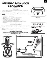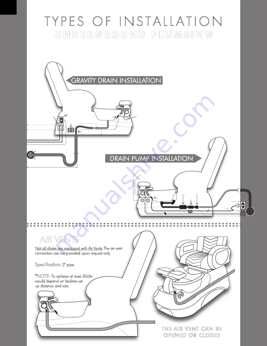
T Y P E S O F I N S T A L L A T I O N
1
1/2
” or 1.5” (4 cm)
4” (10 cm)
26-30” (66-76 cm)
26” (66 cm)
Electrical
Box GFI
Outlet
Distribution Box
Flex Hose
LED Light
Hot/Cold
Water Valve
1/2“ or 0.5” (1 cm)
HOT / COLD
Water Valve
W
A
L
L
1” (2.5 cm)
4” (10 cm)
22” (56 cm)
8cm – 10cm
11/2” or 1.5” (4 cm)
Distribution Box
W
A
L
L
Electrical Box
GFI Outlet
1/2“ (1 cm) HOT / COLD
Water Valve
Electrical Wire
Hot/Cold Water Supply
LED Light
OPTIONAL: Drain Pump Button
OPTIONAL:
Drain Pump
3/4“ (2cm)
PVC Slip
Check
Valve
Pedicure Jet Button
3“ - 4“
Flex Hose
22” (56 cm)
U N D E R G R O U N D P L U M B I N G
The complex diagram below illustrates the ideal placement and sources of both water,
drainage, and electrical power for the NOVO Pedicure Spa Chair. The utilities should be
placed exactly within the footprint of the whole chair.
8
A
I
R
V
E
N
T
S
S
I
D
E
V
I
E
W
THE AIR VENT CAN BE
OPENED OR CLOSED
Not all chairs are equipped with Air Vents. The air vent
connection can be provided upon request only.
Specification:
2” pipe.
*NOTE-
To achieve at least 50cfm
would depend on facilities set
up distance and size.


