Specifications
Electrical (Class 2 Circuits Only)
INPUT
Voltage:
48 VDC ±5% (Isolated)
Power:
62 W (all PoE ports used)
5 W (no PoE ports used)
PoE OUTPUT
Voltage:
48 VDC ±10%
Power:
12.95 W (minimum)
Environmental
Operating Temperature:
0°C to +60°C
Storage Temperature:
– 40°C to +85°C
Humidity, non-cond.:
10% to 95%
Protection:
IP 30
Functional
Compliance: ANSI/IEEE
802.3af
Data Rates:
10, 100 and 1000 Mbps
Signalling: 10BASE-T,
100BASE-TX
and
1000BASE-T
Connectors: Shielded
RJ-45
Segment length: 100 m (maximum)
Mounting
TS-35
DIN-rail
Shipping Weight
1 lb. (0.45 kg)
Regulatory Compliance
CE Mark; CFR 47 Part 15, Class A
UL 508, C22.2 No. 142-M1987
IEEE 802.3af
LED Indicators
Power green
Activity/Link
green or yellow
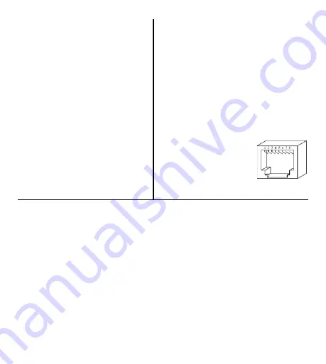
RJ-45 Connector Pin Assignments
All
Ports
Power Added
to PoE Ports
1 BI_DA+
+48
VDC
2 BI_DA–
+48
VDC
3
BI_DB+
48 VDC Return
4 BI_DC+
5 BI_DC–
6
BI_DB–
48 VDC Return
7 BI_DD+
8 BI_DD–
Network Connections
Either straight-through or crossover cables can be used to connect to a non-PoE
Ethernet device that supports Auto–MDI/X or to a PoE powered device. However,
verify that the proper polarity of the PoE power on pins 1, 2, 3, and 6 remains intact.
LED Indicators
The “Power” LED glows solid green when the switch is properly powered. To aid in
troubleshooting, each port has two LEDs. The Port 2 LED labelled “H” glows if a link
exists at 1000 Mbps (green) or at 100 Mbps (yellow). Its LED labelled “L” is normally
unlit but glows yellow if a 10 Mbps link exists. Either the “H” or “L” LEDs flash to show
activity. The LEDs of all other ports are unlabelled but work the same.
Each PoE port has an LED to indicate that the port is delivering power to a PD. The
48V LED indicates proper PoE power and the Fault LED glows red during a PoE power
fault condition.
Summary of Contents for CTRLink EISK8P-GT
Page 3: ...Dimensions ...


