background image

Specifications


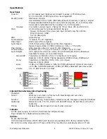
Rear Panel 

  Power In: 


2.1mm coaxial jack (inside center conductor positive), 475 mA maximum 


10.5 to 16.0 VDC, 12 VDC typical (may be unregulated)   

  RS-232 Control: 

DB-9 male connector 


User selectable 300 to 19,200 (9600 default) baud, 8 data bits, no parity, 1 stop bit 


Employs standard ASCII strings from any terminal program, PC, or control system 


Can accept non-standard RS-232, including 0 to +5 VDC operation 


Closures: 

2 momentary closure inputs - Channel Up (Pin 4), Down (Pin 9), GND (Pin 5)   

  IR In: 

3.5mm stereo jack for optional IR-RXC IR Receiver 


   Sleeve= DC power+ from power jack input, limited to less than 100mA 


 Ring=DC power– (GND) 


  Tip= IR data signal 


GND: 

  Grounding 

lug 

  Antenna/Cable: 

'F', female, 75 ohm impedance 

  Video Input:   

RCA female, NTSC composite 

  Audio Inputs:   

2 RCA female stereo unbalanced, 20K ohms impedance  


Maximum level +8dBu, (2V RMS), Reference: 0 dBu = .775 V RMS 

  Video Output:   

RCA composite output, 1V p-p at 75 ohm impedance,  

  S-Video Output:  

Mini DIN 4-pin, Y - 1V p-p at 75 ohms, C - 0.286 V p-p at 75 ohms 

  Audio Outputs:  

5-Pin captive screw terminal, stereo, 200 ohm balanced/100 ohm unbalanced  


Selectable for stereo, mono and SAP modes 


Stereo/SAP:  

Total Harmonic Distortion (THD): 1% maximum, 0.3% typical 


Response: 50Hz to 12KHz, Channel Separation: 25dB minimum, 30dB typical 


Mono:    

Total Harmonic Distortion (THD) 0.5%, 0.1% typical 


Response: 20Hz to 20KHz 


Level:    

+4 dBu (1.2V RMS) balanced, 0 dBu (.8V RMS) unbalanced, typical at max volume 


+11.5 dBu (2.9V RMS) balanced, +8 dBu (2V RMS) unbalanced peak max output 


Volume:  

0 to -70 dB and mute in 64 steps 


Internal Character Generator/Captioning 

 Characters:  

ASCII 

  Format: 

White text over video or white text with black background over video,  


Up to 32 characters, 13 lines 

  Function: 

Closed captioning, channel labels, interactive menus, messages, and system feedback 

  Captioning: 

Modes CC1-CC4, TT1-TT4, On/On with Mute/Off modes, CG text times out to show 

captioning 


Muting: 

Displays blue video image when loss of video is sensed 

Includes 

  12 VDC power supply, 500 mA min (North American shipments only) 

  Plug-in adapter for unbalanced stereo RCA wiring 

Options 

  CC-232 RS-232 Cable 

  IC-RC Wireless IR Remote, IR-RXC External IR Receiver also available (IR In factory-installed option) 

  RK1 Kit for mounting single unit in 19" rack or RK2 Kit for mounting two units side-by-side in 19" rack 

Contemporary Research  


232-STS Stereo S-Video TV Tuner
 

Summary of Contents for 232-STS

Page 1: ...port Road Suite 113 Dallas TX 75252 Phone 972 931 2728 Toll Free 888 972 2728 Fax 972 931 2765 E Mail Sales crwww com Website www crwww com Product Manual 232 STS Stereo S Video TV Tuner Version 4 5 M...

Page 2: ...ions 8 Command String Structure 8 Command and Status Response 8 General RS 232 Commands 9 Character Generator Commands 11 Keypad Channel Command 12 IC RC Remote Emulation 12 Tune Ring Commands and Rep...

Page 3: ...as well as cross color and cross luminance reduction Delivers balanced MTS stereo mono SAP audio with programmable volume bass and treble levels Switches between tuner and composite stereo AV inputs o...

Page 4: ...e higher RF input level specs and best video performance IC RC Remote Control IC RC Optional Keypad Channel selection press Enter to select channel Volume Up Down and Mute Channel Channel Up Down Inpu...

Page 5: ...0 ohm unbalanced Selectable for stereo mono and SAP modes Stereo SAP Total Harmonic Distortion THD 1 maximum 0 3 typical Response 50Hz to 12KHz Channel Separation 25dB minimum 30dB typical Mono Total...

Page 6: ...d they will appear HRC None of the channels work Change to HRC Front Panel Programming To Enter a Front Panel Programming Mode 1 Press and hold the Mute A V button such that the red LED light above is...

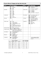
Page 7: ...l up dwn Volume up dwn Channel Volume up dwn Mute A V Channel up dwn Mute A V Volume up dwn Mute A V All Label Mode 14 0 14 1 14 2 14 3 None Alpha only Numeric only Both Power up Volume 5 0 5 X Restor...

Page 8: ...the 232 STS The tuner will accept non standard RS 232 control such as voltage that swings from 0 to 5 VDC commonly found when IR ports are used to send RS 232 commands General protocol specifications...

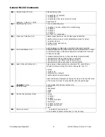
Page 9: ...ct changes Only status operation is affected the functions continue to operate 0 Disable Stereo Mono and Video Loss Detect status default 1 Enable Stereo Mono disable Video Loss Detect 2 Enable Video...

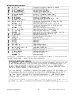
Page 10: ...ramping down VL Ramps volume to level 0 63 Sets volume to specific level VX Volume Mute off Restores audio volume to previous level VV Stop volume ramp Stops volume ramping VT Toggle Volume Mute Alte...

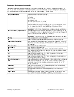
Page 11: ...nt channel label on screen for about 10 seconds DG row column Moves the cursor to the specified row and column position If row is 0 then row will not be changed and if column is 0 then column will not...

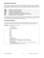
Page 12: ...l entry After 3 seconds with no other key the selected channel will be tuned to Optionally you can have an Enter key send the command KC or KT to select the channel immediately Using the KD command ca...

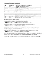
Page 13: ...d Tips Leading zeros may be included or omitted from command parameters Example TC 009 Selects channel 9 as A V output same as TC 9 Multiple commands may be concatenated as single strings up to 120 AS...

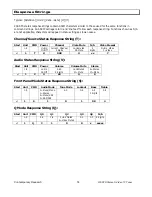
Page 14: ...ng T Start Unit CMD Power Channel Video Mute N A Video Present 1 9 U On M Off Current Channel 3 digits U Unmuted M Mute 2 digits N No Video Y Video 1 T U 008 U xx Y Audio Status Response String V Star...

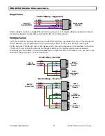
Page 15: ...t the first unit in the RS 232 chain to the highest Unit then wire in sequence to the last tuner in the chain The reason for this is that CR tuners use an intelligent data bus the highest number tuner...

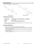
Page 16: ...r 4 supplied 8 32 by black countersunk screws RK2 Side by Side Rack Kit 1 Remove top cover of the first unit by removing the ten 10 black screws 2 Attach cover of first unit to the side of the second...

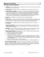
Page 17: ...r electric shock 7 Object and Liquid Entry Never push objects of any kind into this product through openings as they may touch dangerous voltage points or short out parts resulting in a fire or electr...

Page 18: ...er damages are sought or a claim is made under this warranty or as a tort claim including negligence and strict product liability a contract claim or any other claim This limitation of liability canno...

Reviews: