background image

Contemporary Research                                             3    

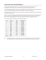
ICC2-ATSC 4S 


Setup Guide


All instructions for the ICC2-ATSCS applies to the legacy ICC2-ATSC 4. Setup tools include: 


HD2-RC Remote Mode (accesses On-Screen Graphic Menus and special HD functions) 


IC-RC Remote Mode (accesses on-screen Text Menus) 


Front-Panel Setup 


ICC-Net commands from Display Express, iC Send software, or custom control system 

The ICC2-ATSC 4S is designed to offer advanced analog/digital tuning, yet be compatible with existing iCC-Net systems.  
 

IR Remote Operation 

The optional HD2-RC IR Remote is designed for control and setup of ATSC-series HDTV tuners, and normally, the tuner will 
respond to the remote in the same way as other ATSC-series tuners. 
 
There is a special IC-RC mode that can be set from the front-panel menus. This will activate the on-screen text menus to 
set the device address and control type, and a few other special functions. When the settings are done, the tuner can be 
set back to normal HD2-RC operation. 
 

Front-Panel Setup


The Front Panel modes are useful for setting tune mode, channel scan, HD output and resolution, switching between IC 
and HD2 remote modes, and setting the device address and control type, and other options. 

IC Send/ICC-Net Control 

You’ll find the free IC Send program to be a great tool for system setup and testing, especially if the site is using the ICE

-HE 

Head End and your laptop is configured for the site’s network. You 

can also use a PC or laptop via RS-232 with the ICC-HE 

Head End. Key functions include:


On, Off and Tune

 commands to test operation to one or all ICC2-ATSC 4S units. 


IR Mode

. Switch all tuners to IC or HD2 modes. 


Channel Setup

. Use the T^ Command to force all units to scan channels, then use the XA and XD commands to 

add and remove channels from the list. If you’re using RS

-232 control at the head end, have an ICC2-ATSC 4 at 

that location to check your setup.  


Tuner Setup.

 Use LM and TM commands to configure general tuner operation. 


Default Input.

 Use the ER command to set the default input.  


Control Type.

 Change RS-232 control type and baud rate 


Device Address Settings


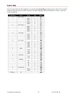
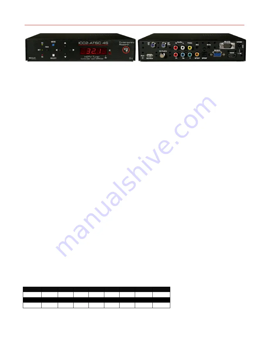
Use the front-panel setting 2 and 3 to set the address. Menu 3 sets the Zone address, and Menu 2 sets the individual 
number in the zone. For example the system address for a controller is 257, set Menu 2 to 2.1 (1), and Menu 3 to 3.1 
(Zone 1, which is address 256), 1 + 256 = 257 system address. The controller will act by itself when you send the unique 
257 code, as a zone group when you send 256, or from address 4095 (All). 


Zone 


256 

512 

768 

1024 

1280 

1536 

1792


2048


Zone


10 

11 

12 

13 

14 

15 


2304 

2560 

2816 

3072 

3328 

3584 

3840 


Summary of Contents for ICC2-ATSC 4

Page 1: ...Contemporary Research 1 ICC2 ATSC 4S Product Manual ICC2 ATSC 4S ICC2 ATSC 4 HDTV Tuner Controller October 3 2017 S12 Control Version 6 9 HD Processor Version 6 38...

Page 2: ...riting Your Own Control Code 11 iCC Net Commands 12 Control 12 Tuning 13 Tuning 14 Text 14 HD2 RC Remote Emulation 15 iCC Net Response 16 iCC Net Zones Units and Device Addresses 17 System Map 18 On S...

Page 3: ...et Control You ll find the free IC Send program to be a great tool for system setup and testing especially if the site is using the ICE HE Head End and your laptop is configured for the site s network...

Page 4: ...hts Hold down SELECT on the remote Pressing 4 selects normal 38 KHz IR pressing 9 selects 57 KHz IR Check the front panel R Receive menu to see if it is turned on or off If there is significant IR int...

Page 5: ...arate channels lists for each You ll need the optional RF AB switch which has a mini 3 5mm cable that connects to the A C control output on the back of the tuner The placement of RF connections on the...

Page 6: ...Unit Zone 256 Panel Lockout 4 0 Reserved performed by LM command Power up Volume 5 0 5 N Restore previous level default 1 63 sets volume level Firmware Version 6 68 Ex Version 2 0 Channel Up Dwn to se...

Page 7: ...Sharp Monitor 9600 LC46LE820UN 44 Projection Design Projector 9600 45 Extron Wall Panel 9600 Emulates buttons on Pole Vault wall panel 46 Sharp Monitor 9600 PN L702B PN V601 47 Sharp Monitor 9600 LC70...

Page 8: ...ith the remote s numeric keypad then hit Enter to save the new number The setting will use the default baud rate which can be changed using front panel menus 45720 Set Display Projector Input Enter co...

Page 9: ...evCh can be used to access and recall channels Menu Operation Press Menu to access the on screen menus Use the directional Arrows Select and Exit to navigate the menus List displays the list of all ch...

Page 10: ...et to IP port 2728 The USB port is typically used to provide RS 232 control from a PC with Display Express software Command String Structure Characters in command strings are expressed in a combinatio...

Page 11: ...1 15 hex 1 F Unit 1 255 hex 1 FF Bytes Number of bytes that follow Command 1 byte Parameters 1 to 4 bytes String Format Every software application has a different denotation for handling hex ASCII an...

Page 12: ...lects front panel buttons operation 0 enabled 1 disabled Operating Parameters TM A5 dh dl 3 TM setting 7 bytes Sets up key functions in the unit Bit 0 Alpha channel labels 0 alpha labels off 1 alpha l...

Page 13: ...s for digital only deletes analog channels 2 Scans for digital only keeps analog channels 3 Scans for analog only deletes digital channels 4 Scans for analog only keeps digital channels Channel Scan T...

Page 14: ...t including carriage returns 28 characters per line Use a hex 0D or decimal 13 in the text as a carriage return which will advance CG to the next line first space on the right Start Line 1 9 Text Colo...

Page 15: ...6 17 7 18 8 19 9 20 21 Enter 22 Ch Up 23 Ch Dn 24 Vol Up 25 Vol Dn 26 Vol Mute tog 27 Power On 28 Power Off 29 Menu 63 Guide 80 Freeze 81 Signal 82 Ratio 85 Audio 88 Favorite 95 List 96 Add Delete Cha...

Page 16: ...it 2 1 The Channel Up Down responses will be sent if the Tune Ring contains no channels see Ex2 in the Tune Ring command section IR Menu M dh dl 5 M msh msl mph mpl 9 bytes Sent when unit receives a n...

Page 17: ...e at time If you need to turn off all 50 TV in a zone you would need to send 50 commands In addition to the hassles of creating multiple commands there would be a long delay between the first and last...

Page 18: ...ication iCC Net Zone Zone Room Unit Device 1 W 1st Floor 256 W151 1 257 W152 2 258 W153 3 259 W154 4 260 2 W 2nd Floor 512 W251 1 513 W252 2 514 W253 3 515 W254 4 516 3 E 1st Floor 768 E151 1 769 E152...

Page 19: ...to Scan Starts scan of analog and digital channels for Air looks for NTSC and ATSC channels Cable Auto looks for analog and digital QAM cable channels as well as all frequency plans Cable STD standard...

Page 20: ...hout affecting the others Signal Strength This page also displays from the Signal remote command The graphic shows the current signal strength and changes in real time This allows you to monitor the s...

Page 21: ...Movie and TV rating allowed Setup Menus This series of menus select the options for tuner operation Screen Format 16 9 or 4 3 NOTE Set when tuned to a digital channel again when tuned to an analog cha...

Page 22: ...d choose on or off Note The DST trigger comes from the broadcast stations and may not be in sync with the new US standards Use On Off or time zone to offset time Time Zone Select local time Zone Time...

Page 23: ...the RF Coax Networking Communicates with Display Express Web software and custom control systems via iCC Net RF protocol Universal Tuning Handles a mix of ATSC clear QAM MPEG and MPEG4 H 264 and NTSC...

Page 24: ...2 0 51mm height 1 5 RU x 8 0 203mm deep Weight 1 94 lbs 890 g Enclosure Steel with black powder coat paint Mounting 1 5 RU rack kits no longer available Front Panel Display Red LED Channel Display dot...

Page 25: ...leeve DC power from power jack input limited to less than 100mA Ring DC power GND Tip IR data signal Power In 2 1mm coaxial jack inside center conductor positive 1 1 A maximum 11 5 to 15 VDC 12 VDC ty...

Page 26: ...product from the wall outlet and refer servicing to qualified service personnel under the following conditions When the power supply cord or plug is damaged If liquid spills or objects fall into the p...

Reviews: