background image


Trouble Shooting 


61


Trouble Shooting  


This section describes trouble-shooting procedures for the most common issues that can arise with your scanner. Please 
look for a problem description that matches your actual situation. If found, perform the recommended trouble-shooting 
procedures before requesting a service call. 

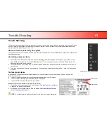
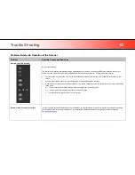
How are errors reported on your system 

The scanner panel‟s

 Error Indicator 

will blink when the scanner detects an error. WIDEsystem will report the nature of the 

error on your screen.  

Correcting common errors 

1.  The actual nature and cause of the error may be reported immediately through a message on your screen. If not, 

open WIDEsystem (double--click the WIDEsystem icon 

 on your system tray) and select the Status tab to view 

additional information about the error.  

2.  The information on your screen may include instructions and actions to remedy the error. Follow the instructions on 

your screen.   

3.  Look for a description of the error and remedy 

in this users guide‟s trouble shooting section. Follow the instructions 

provided.   

Technical assistance 

In some cases you may need technical assistance. You should contact your service provider if one or more of the 
following cases is true: 
a.  … the error cannot be remedied through the action suggested on your PC screen. 
b. …  the error and its remedy is not described in this users guide.  
c.  … the system fails to report the error on your screen. 
 
Before calling technical assistance prepare the following: 
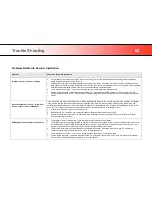
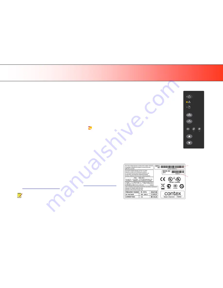
4.  Write down your scanner model and serial number. The serial number is printed on 

a label on the back of the scanner. 

5.  Write down your Firmware version. See the section 

How to identify the firmware 

version running in the scanner?

.


NOTE:

 Y

our manufacture‟s website contains service provider contact information.  


Error detected 

– Error indicator blinks 


Serial Number 

Model Number 

Summary of Contents for HD Ultra Series

Page 1: ...Model HD Ultra series User s Guide Wide Format Scanners...

Page 2: ...e scanner panel 31 Batch scanning 31 Monitoring your scanner with WIDEsystem 32 Scanning Thick Media 34 Automatic Thick Media Adjustment ATAC 34 When Scanning in Thick Media Positions 35 Maintenance 3...

Page 3: ...Help After installing your drivers open WIDEsystem and press F1 Contains information on using the WIDEsystem software IMPORTANT Be sure to use the WIDEsystem TOOLS CD ROM that came with your scanner...

Page 4: ...button and indicator ATAC up button Thick media Paper Forward button Error indicator Paper backwards button ATAC down button Thick media Scan Application Email Application Copy Application One touch...

Page 5: ...canner 4 Scanner Rear View Parts you need to recognize when installing and using the scanner Paper return guides Paper Pressure Adjustment lever Main Power switch and power socket Interface connection...

Page 6: ...ftware Grounded power outlet PC with USB port or enabled Gigabit port NOTE Gigabit interface compatibility and speeds depend on your scanner model Installation Steps To get your scanner up and running...

Page 7: ...plete installation 3 Remove the CD when done with installation 4 To verify correct installation of WIDEsystem the WIDEsystem icon will be visible in your system tray 5 After installing WIDEsystem inst...

Page 8: ...area with the original Cleaning the scanner Open the scanner lid Press the lid release buttons upwards The internal scan area should be wiped clean for any dust accumulated during packaging and shipp...

Page 9: ...ernal scan area s glass plate free of dust Use a dry lint free cloth If you detect difficult smudges on the glass that cannot be wiped clean with a dry cloth refer to this guide s section Cleaning the...

Page 10: ...ect power cable Connect the scanner to a power outlet Connect the power plug end of the scanner power cable to a power outlet CAUTION The scanner is equipped with a three wire pin grounding type plug...

Page 11: ...r on its left side when facing the back 2 Connect the B connector end square shaped end to a USB port on the scanner NOTE For Gigabit enabled scanner models The installation wizard will instruct you o...

Page 12: ...t on the back of the PC Using USB ports on the front can affect performance on some PC models Scanner installation The Installation Wizard starts up 1 The driver will detect the scanner and start the...

Page 13: ...s be sure to select YES if Windows asks you to allow the software to access the network Scanner Installation Set energy star idle time preference On delivery the scanner is set for automatic entry int...

Page 14: ...itionally require an activation code Activation codes can be obtained from your dealer or through the manufacturer s License website Follow the instructions Manual Activation below to obtain an activa...

Page 15: ...vation method the dialog shown on the top right appears 1 Enter you license key in the designated field 2 The key will be authenticated online right after it is entered and if valid a green tick will...

Page 16: ...enter an activation code in the empty field Click Next to obtain an activation code 2 The Manual activation wizard will display instructions Please note the actual scanner s ID hardware ID or S N seri...

Page 17: ...Change the scanner s network name optional NOTE This step only appears with licensed Ethernet supported scanners as detected during activation You may wish to change the default name of the scanner t...

Page 18: ...area glass as instructed in the previous installation steps then do so now 4 You will be asked to insert your calibration sheet that came with the scanner 5 Be sure to align the sheet arrow with the s...

Page 19: ...y when you see this message For models that supports Gigabyte proceed to the steps for enabling gigabyte on the scanner plus sharing it on the network For USB only scanners you can also choose to shar...

Page 20: ...r Ethernet interface socket at the scanner s back 3 Connect the other end of the gigabit cable to your LAN 4 Open WIDEsystem if not already open double click the WIDEsystem icon in the system tray 5 P...

Page 21: ...1 Make sure your PC with the scanner connected via USB is connected to the LAN 2 Double click on the WIDEsystem program icon and select the Network tab 3 Select the option Share the scanner on the ne...

Page 22: ...and 0 for OFF The scanner s Self Test Procedure When you turn the main power ON the scanner runs a short self test procedure This takes less than one minute The 3 LEDS on the panel will be on during t...

Page 23: ...to wake mode Automatically with the Timer see Automatic Power functions When you feed a document into the scanner When you press any button on the panel Scanner in Wake mode Power LED is green Advanta...

Page 24: ...atically after idle time option In order to use automatic power management functionality the scanner Main Power switch at the scanner s back must be turned ON The power LED on the operator s panel wil...

Page 25: ...Esystem the Timer tab will display the values currently stored in the scanner If the scanner is being used it will delay entry into Sleep mode The power LED on the panel will blink just before entry i...

Page 26: ...he panel or inserting a document for scanning Sleep by pressing and holding down the power button for 3 seconds You can choose to disable automatic entry into Sleep mode entirely if you want only manu...

Page 27: ...e original at the scanner s right edge Paper ready LED lights green when paper is engaged Adjust the left paper guide to support a straight scan path You can use automatic loading or manual loading Th...

Page 28: ...adjust to the paper width 1 The left side paper guide can be place anywhere on the scanner bed Special adhesive will hold it in place 2 Place your document with the right edge against the right paper...

Page 29: ...nts or when you want time to align the document before it is fed 1 Make sure the paper handling option Manual is set in your scanning application 2 Align the right edge of the document with the right...

Page 30: ...in the scanner With the Fast load option selected the original is pulled only under the first roller axle and scanning will start from there The Fast load option is convenient for batch scanning of o...

Page 31: ...sure position Reduced paper pressure position Paper pressure Lever back right side of scanner Setting the input size The Input size defines the scan area You enter the input size in your application s...

Page 32: ...a scan is initiated and the result is loaded into the application triggered You configure your one touch buttons through WIDEsystem and your compatible scanning software Please refer to the on line h...

Page 33: ...n relation to firmware and hardware revisions Open the Info tab Install new firmware You download new firmware to a folder on your machine Then right click on the scanner icon select Advanced Options...

Page 34: ...ave a valid license for the activation upgrade Launch the scanner calibration wizard Right click on the scanner icon select Calibrate Launch the WIDEsystem on line help To find instructions on trouble...

Page 35: ...ill require you use the ATAC functionality To adjust the insertion slot for thick media with ATAC 2 Press and hold down the ATAC Up key on your operator s panel to raise the pressure platen and enlarg...

Page 36: ...timal speed in the Normal position To allow secure drive handling scanning speed is automatically reduced when the scanner is in the extended thickness positions Modifying Stitching Parameters Thick s...

Page 37: ...reaks in the end result See more under the section Cleaning the scan area 2 Calibration and camera alignment Scanner Calibration is easy to perform and most of it is completely automatic Scanner calib...

Page 38: ...e key points parts and areas you need to recognize when cleaning the scanner or changing parts Instructions follow in the next sections Lid latch lever to open lid Red strip to access the white backgr...

Page 39: ...pper and lower rollers Caution do not use abrasives acetone benzene or fluids that contain these chemicals Do not spray liquids directly onto the scanner glass plate or anywhere else in the scanner Ca...

Page 40: ...er lid release buttons are at each side of the scanner lid 1 Stand at the front of the scanner 2 Simultaneously place a thumb under each lid release button and push them upwards until you feel the lid...

Page 41: ...per rollers The white background platen white metal area is fixed in the scanning area lid The upper rollers are aligned in 2 rows on each side of the white background platen 1 Hold the lid in its ope...

Page 42: ...ss cleaner Apply the cleaner to cloth and wipe the lower rollers in both rows 2 Dry the lower rollers completely using a separate clean dry lint free cloth Caution Do not spray liquids directly onto t...

Page 43: ...scanner feeding bed surface so dirt and dust are not dragged into the scan area with the original Cleaning the scan area Cover when not in use Cover the scanner with its plastic dust cover when not in...

Page 44: ...insert a calibration sheet Other than that scanner calibration is completely automatic NOTE Cleaning and calibration are tied together Cleaning the scanner creates the need for renewed calibration an...

Page 45: ...tem tray to open the WIDEsystem program 2 Press the Calibrate button Calibration Select the Calibration type Select either Camera Alignment or Full Calibration Camera Alignment will align horizontal c...

Page 46: ...program works in steps to analyze and correct the status of the sensors calibrate black and white values and calibrate color on color scanners The calibration sheet will be rescanned a number of times...

Page 47: ...ing WIDEsystem WARNING FLAG glass plate and White background platen replacement After receiving a warning by WIDEsystem and replacing the part be sure to reset the part replacement warning flag throug...

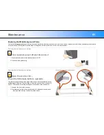
Page 48: ...buttons upwards The internal scan area should be wiped clean for any dust accumulated during packaging and shipping The scan area is under the scanner lid so you have to open it The scanner lid releas...

Page 49: ...Hold the lid as you ease it all the way back to expose the scan area and glass plate Replacing the glass plate Pull back the glass plate levers 1 Locate the glass plate levers on each side of the glas...

Page 50: ...s axis 1 With both arms pull simultaneously on the left and right levers to tilt the glass plate towards your body on the round pin s axis 2 Tilt the glass plate back on the hooks until it is complete...

Page 51: ...on each side of the scanner 2 While supporting the glass plate with fingers on the lever handles carefully ease the glass plate down backwards away from your body so it falls into place 3 Close the s...

Page 52: ...in power switch scanner back to OFF 2 Disconnect the power plug Replacing the white background platen Open the scanner lid Press the lid release buttons upwards The internal scan area should be wiped...

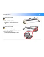
Page 53: ...to expose the underside of the lid Replacing the white background platen Locate the red cover strip The white background platen is in the scanner lid You need to access the platen s edge to slide it...

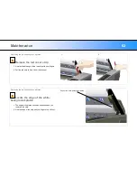
Page 54: ...th your fingers 2 Pull the red strip to free it from the scanner 1 2 Replacing the white background platen Locate the edge of the white background platen 1 The edge of the platen becomes exposed when...

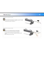
Page 55: ...pull the strip out of the scanner lid Replacing the white background platen Insert a new white background platen 1 Reverse the steps to insert your new white background platen 2 Carefully slide in a...

Page 56: ...Reattach the red strip in its place 2 Close the scanner lid until you hear the locks click shut NOTE It is recommended to recalibrate after changing the white background platen NOTE Remember to reset...

Page 57: ...ors can be obtained through your dealer WIDEsystem monitors lamp usage and will warn you when it is time for a replacement Replacing the scanner lamp Turn scanner power off and disconnect the scanner...

Page 58: ...The edge of the lamp unit will be exposed and accessible Replacing the scanner lamp Remove the old lamp unit A lamp unit consists of a fluorescent lamp that is mounted in a metallic reflector brace wi...

Page 59: ...lamp edge power connector side on the tracks 2 Carefully push the lamp unit into the scanner along the tracks 3 Be sure to insert the lamp unit all the way so the internal power connections engage wit...

Page 60: ...tab into the corresponding notch on the scanner 2 Snap the cover shut NOTE The cover must always be closed before turning scanner power ON NOTE Remember to reset the lamp replacement warning flag tho...

Page 61: ...em double click on the system tray s WIDEsystem icon 2 Select the Info tab 3 The Info tab displays useful data about your scanner firmware 4 Firmware release Upgradeable firmware version 5 Firmware do...

Page 62: ...may include instructions and actions to remedy the error Follow the instructions on your screen 3 Look for a description of the error and remedy in this users guide s trouble shooting section Follow...

Page 63: ...be entered on the system as a new device without functional drivers If this is the case the scanner will be displayed in the Windows Device Manager with a yellow error icon The scanner entry must be...

Page 64: ...a description of the error in this users guide Follow the instructions provided In some cases you may need technical assistance You should contact your service provider if one or more of the following...

Page 65: ...s not eject respond to pressing the keys you will need to open the scanner lid to remove it 3 Simultaneously place a thumb under each lid release button and push them upwards until you feel the lid s...

Page 66: ...ur technical service provider if the problem persists Error message Unable to Adjust Camera 1 Control that the scanner is set for Normal lowest media thickness The scanner s pressure platen must not b...

Page 67: ...naccessible You need reboot the scanner to Safe Mode to reapply the firmware Restart the scanner If the scanner detects corrupted firmware it will start up in Safe Mode Confirm Safe Mode Open WIDEsyst...

Page 68: ...riginals can give distortions when the front edge meets the exit rollers or the trailing edge leaves the entry rollers To omit this the leading and trailing edges are by default skipped when in one of...

Page 69: ...e cabinet at the back or bottom are provided for ventilation This ensures reliable operation of the product and protects it from overheating These openings must never be blocked or covered The opening...

Page 70: ...ications Operation of this equipment in a residential area is likely to cause harmful interference in which case the user will be required to correct the interference at his own expense Caution Pursua...

Page 71: ...tes that this toxic or hazardous substance contained in all of the homogeneous materials for this part is below the limit requirement in SJ T11363 2006 SJ T11363 2006 X Indicates that this toxic or ha...

Reviews: