background image

5

Form No. 256827   Rev. 11/08

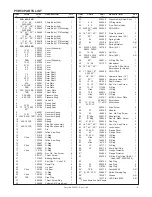
 ITEM 

CODE 

PART 

DESCRIPTION 

QTY 

  NO. 


NO. 


REQ’D

    32A, 42A, 50B 

  1 

17, 21, 22, 

550615 

Pump Body (Std.) 


2400, 2500 

  1  18** ,24** ,25**  550641 

Pump Body (Std.) 

  1 

17, 21, 22, 

550640 

Pump Body (“D” Mounting)  1 


2400, 2500 

  1  18** ,24** ,25**  550642 

Pump Body (“D” Mounting)  1 


70B 

  1 

17, 21, 22, 

550616 

Pump Body (Std.) 

  1  18**, 24**, 25**  550617 

Pump Body (Std.) 

  1 

17, 21, 22, 

550618 

Pump Body (“D” Mounting)  1 

  1  18**, 24**, 25**  550619 

Pump Body (“D” Mounting)  1


32A, 42A, 50B 

  2 


500124 

Cover (Standard) 

  2 

13, LF 

500230 

Cover 

  2 

21, 31 

508451 

Cover 

  2 

22 

508441 

Cover 

  2 

23 

550930 

Cover 


  2 

70B


504897 

Cover (Standard) 

  2 

13, LF 

507588 

Cover 

  2 

21, 31 

550171 

Cover 

  2 

22 

550139 

Cover 

  2 

23 

550928 

Cover 

1

  3 


550184 

Rotor Shaft 

  3 

13 

550295 

Rotor Shaft 

  3 

21 

550183 

Rotor Shaft 

  3 

22, 31 

550296 

Rotor Shaft 

  3 

23 

550944 

Rotor Shaft 

1

  4 

32A 

402001 

Port Plate 

  4 

42A, 70B 

404384 

Port Plate 

  4 

50B 

404418 

Port Plate 

1

  5  32A, 42A, 50B  503335 

Thrust Plate 

  5 

70B 

504899 

Thrust Plate 

1

  6 

32A, 50B 

034460 

Pressure Ring 

  6 

42A, 70B 

302221 

Pressure Ring 

1

  7 


256803 

Vane Kit 

1

  8 


308439 

Spring Seat 

  8 

3L, 5L 

307853 

Spring Seat 

  8  17, 18**, 2500  351188 

Spring Seat 


25**

  9 


262957 

Governor Spring 

  9 

3L, 5L 

114414 

Governor Spring 

  9  32A15, 42A, 70B  129143 

Governor Spring 

1

  10 


162823 

Spring 

  10 

42A15, 70B 

162824 

Spring 

1

  11 


122404 

Ring Shoe Assembly 

  11 

42A15, 70B 

130582 

Ring Shoe Assembly 

1

  12 


130041 

Pin 

1

  13 


120805 

Teflon Seal Ring 

1

  14 


121619 

O-Ring 

  14 

Viton 

130608 

O-Ring 

1

  15 


122340 

Teflon Seal Ring 

1

  16 


130607 

O-Ring 

  16 

Viton 

130609 

O-Ring 

1

  17 


108991 

O-Ring 

  17 

Viton 

110134 

O-Ring 

1

  18 


198324 

Soc. Hd. Cap Screw 

8

  19 


302127 

Thrust Screw 

1

  21 


121090 

Bearing Bushing 

2

  22 


012137 

Key (Add 1 - Code 13) 

1

  23 


260380 

Dowel Pin 

4

  24 


121600 

Lip Seal 

  24 

Viton 

122169 

Lip Seal 

2

  25 


153111 

O-Ring 

  25 

Viton 

162100 

O-Ring 

1

  26* 

70B 

123328 

Pipe Plug 

2

  27 


250368 

Thrust Screw Plug 

1

  29 


256486 

Volume Adj. Screw Ass’y. 

1


ITEM 

CODE 

PART 

DESCRIPTION 

QTY 

  NO. 


NO. 


REQ’D

  30 


250240 

Pressure Adj. Screw Ass’y.  1

  31 

8, 9 

256509 

O-Ring Union 

1

  32 

8, 9 

256508 

Flow Control Valve 

1

  33  2400, 24**, 2500  350945 

PMA-24B-A 


25**

  34  18**, 24**, 25**  256510 

Flare Connector 

2

  37 

24** 

256889 

Hydraulic Hose (20”) 

1

  39 

5L 

255592 

Spring Guide 

2

  40 

5L 

123186 

Shim (.010) 

A.R.

  41 


308691 

Spring Retainer 

1

  44  32A15, 42A15,  163786 

Shim (.010) 

A.R. 


50B15, 70B15

  45 

15, 36 

004262 

Roll Pin 

1

  46  32A15, 42A15,  257850 

Shim (.060) 

A.R. 


50B15, 70B15

  48 

25** 

256514 

O-Ring Run Tee 

1

  49 

15, 36 

301737 

Handwheel 

1

  50  18**, 24**, 25** 


Valve (Ref.- See Valve  


Escutcheon for Model) 

  51  17, 1800, 18**,  350946 

PMA-17B-A 


2500, 25**

  52 

18** ,25** 

256888 

Hydraulic Hose (16”) 

1

  53 

25** 

256894 

Hydraulic Hose (28”) 

1

  56 

13, LF 

401995 

Seal Retainer 

1

  57 

13, LF 

198278 

Soc. Hd. Cap Screw 

3

  58 

13, LF 

111298 

O-Ring 

  58 

Viton 

112222 

O-Ring 

1

  59 

70B 

260411 

O-Ring 

  59 

Viton 

109780 

O-Ring 

4

  61 

1800 

210721 

MC03-A Cover Plate 

1

  66 


309961S  Escutcheon 

  66 

13, 21, 22, 

111431S  Escutcheon 


23, 31, LF

  67 


250597 

Drive Screw 

4

  69 

23 

450720 

Adapter 

1

  70 

23 

199682 

Hex. Hd. Cap Screw 

6

  80 

“D” Mtg. 

350810 

Adapter Ring 

1

  81 

“D” Mtg. 

198820 

Pan Hd. Mach. Screw 

2

  82* 

21, 23, 31 

008446 

Cap Plug 

2

  83  18**, 24**, 25**  198225 

Soc. Hd. Cap Screw 

4

  84  18**, 24**, 25**  012144 

Lockwasher 

4

  85 

21, 23, 31 

147655 

Flange Cover 

  85 

22 

164598 

Flange Cover 

1

  86 

21, 23, 31 

120689 

O-Ring 

  86 

Viton 

141714 

O-Ring 

1

  87 

22 

146493 

O-Ring 

  87 

Viton 

154132 

O-Ring 

1

  88 

LF 

147177 

O-Ring 

1

  89 

LF 

350179 

Pump Bolt Plug 

1

  90* 


254832 

Flange Protector 

1

  91* 


254833 

Flange Protector 

1

  92 


256708 

O-Ring Plug (Viton) (Add 1  1 


 - Code 1800, 2400, 2500)

  93 


256744 

Cap Plug 

1

  94 

22 

008345 

Cap Plug 

  94 

23 

119799 

Cap Plug 

2

  95* 

70B 

258775 

Loctite #262 

A.R.

  97*  21, 22, 23, 31  258693 

Spline Warning Tag 

1

  98* 


143391 

Grease 

A.R.

  99* 


132779 

LED Plate #250 

A.R.

    * These Items Are Not Shown

PVR50 PARTS LIST

Summary of Contents for PVR50 Flanged Series

Page 1: ...nameplate See Figure 1 for the location of the Ordering Code This service manual applies to products with Ordering Codes like the sample in Figure 2 INSTALLATION PUMP DRIVE AND MOUNTING When mounting the pump and motor care must be taken to align the pump and motor shafts within 003 T I R Direct inline through a jaw type flexible web coupling is recommended for all Continental pumps Tire type flex...

Page 2: ...corresponding to the case drain in the pump or manifold If connected to a heat exchanger the case drain line should be protected with a 10 psi 7 bar maximum relief valve in parallel with the heat exchanger No other return lines should be connected in common with the case drain return 5 Rotate pump and motor by hand to insure free rotation 6 Set the machine controls to open the circuit and allow fr...

Page 3: ...low for this step 3 See Pressure and Volume Adjustment Sensitivity chart below 4 Deadhead the pump then turn the volume screw the proper number of turns to obtain the flow desired 5 Return pump to flow condition and check flow rate If output flow is incorrect switch pump to deadhead and readjust per above CAUTION Turning the maximum volume control in too far can force the pressure ring over center...

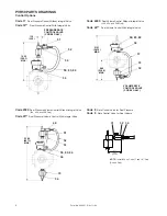
Page 4: ...ns Mechanical Options PVR50 PARTS DRAWINGS 14 12 358 7 22 88 89 66 67 56 57 58 24 2 3 Code LF Only INTERNAL SPLINE 66 67 86 or 87 2 3 Code 21 Tandem Pump Mounting 9 Tooth Spline A Mounting Code 22 Tandem Pump Mounting 13 Tooth Spline B Mounting Code 23 Tandem Pump Mounting 14 Tooth Spline C Mounting Code 31 Tandem Pump Mounting 13 Tooth Spline A Mounting Code 13 Double End Drive Shaft Code LF Left...

Page 5: ...ip Seal 2 25 153111 O Ring 1 25 Viton 162100 O Ring 1 26 70B 123328 Pipe Plug 2 27 250368 Thrust Screw Plug 1 29 256486 Volume Adj Screw Ass y 1 ITEM CODE PART DESCRIPTION QTY NO NO REQ D 30 250240 Pressure Adj Screw Ass y 1 31 8 9 256509 O Ring Union 1 32 8 9 256508 Flow Control Valve 1 33 2400 24 2500 350945 PMA 24B A 1 25 34 18 24 25 256510 Flare Connector 2 37 24 256889 Hydraulic Hose 20 1 39 ...

Page 6: ...ral Valve 32A 42A and 50B Only Code 25 Dual Pressure Volume Control With Integral Valve Code 8 Rate Control Valve for Dual Pressure Code 9 Rate Control Valve for Dual Volume PVR50 PARTS DRAWINGS Control Options 9 40 238 8 MAX 21 31 541 3 MAX VOLUME RATE CONTROL VALVE CODE 9 ONLY 37 33 50 83 84 34 34 23 90 607 1 MAX 37 33 50 83 84 34 53 34 52 51 48 14 50 368 3 MAX PRESSURE RATE CONTROL VALVE CODE 8...

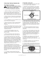
Page 7: ...he housing should be pressed out from the front The cover bearing should be pulled out using an expanding type puller The bearings should not be reused once they have been removed 11 It is unlikely that further disassembly will be necessary in order to perform routine maintenance on the pump REASSEMBLY PROCEDURE 1 Clean and inspect parts to determine which parts are worn enough to require replacem...

Page 8: ...e bore in the thrust plate is concentric to the bearing bore in the cover If the bores are not concentric the thrust plate must be rotated 180 on the locating pins 11 Assemble the cover 2 and thrust plate 5 onto the housing 1 and align the bolt holes Rotate the shaft as the cover bolts 18 are tightened to assure that the vanes are not cocked 12 Torque the cover bolts to 100 lbs ft The shaft should...

Reviews: