IO-240 Series Engine Installation & Operation Manual
2-5
31 October 2011
Engine Description
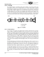
The flange type crankshaft has a propeller mount flange forged on the front end with six
tapped bushings pressed into holes spaced equally around the flange. Six bolts, screwed
into the shaft flange bushings, clamp the propeller between a loose front flange and the
shaft flange.
Figure 2-5. Crankshaft
2-2.2.2. Connecting Rods
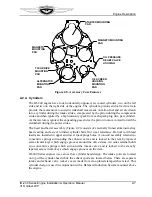
The connecting rods halves (Figure 2-6) are machined from a single forging of aircraft
quality steel and cut into two pieces, splitting the center of the larger opening of the
connecting rod assembly. The resulting pieces, called the rod and cap are fitted with a two
piece bearing and attach to the crankpin or rod journal with special bolts and nuts.
The portion of the rod between the rod and the crankpin and piston pin ends is called the
“I” beam. A split steel-backed bronze bushing is pressed into the piston pin end and
machined for a precision pin-to-bushing fit.
Figure 2-6. Connecting Rod
CRANKSHAFT
FLANGE
FRONT MAIN
JOURNAL
ROD JOURNAL
ROD JOURNAL
ROD JOURNAL
REAR MAIN
JOURNAL
MIDDLE MAIN
JOURNAL
OIL
PASSAGE
#1
#2
#3
#4
OIL
PASSAGE
CRANKSHAFT
FLANGE
FRONT MAIN
JOURNAL
ROD JOURNAL
ROD JOURNAL
ROD JOURNAL
REAR MAIN
JOURNAL
MIDDLE MAIN
JOURNAL
OIL
PASSAGE
CRANKSHAFT
FLANGE
FRONT MAIN
JOURNAL
ROD JOURNAL
ROD JOURNAL
ROD JOURNAL
REAR MAIN
JOURNAL
MIDDLE MAIN
JOURNAL
OIL
PASSAGE
#1
#2
#3
#4
OIL
PASSAGE
NOTE: Some older models use castellated nut with cotter pin
SPIRAL LOCK NUT
BRONZE BUSHING
CONNECTING ROD
CONNECTING ROD
CAP
ROD BOLT
SHELL
BEARING
Summary of Contents for IO-240-A
Page 145: ......
Page 146: ...www continentalmotors aero ...


