IO-240 Series Engine Installation & Operation Manual
2-7
31 October 2011
Engine Description
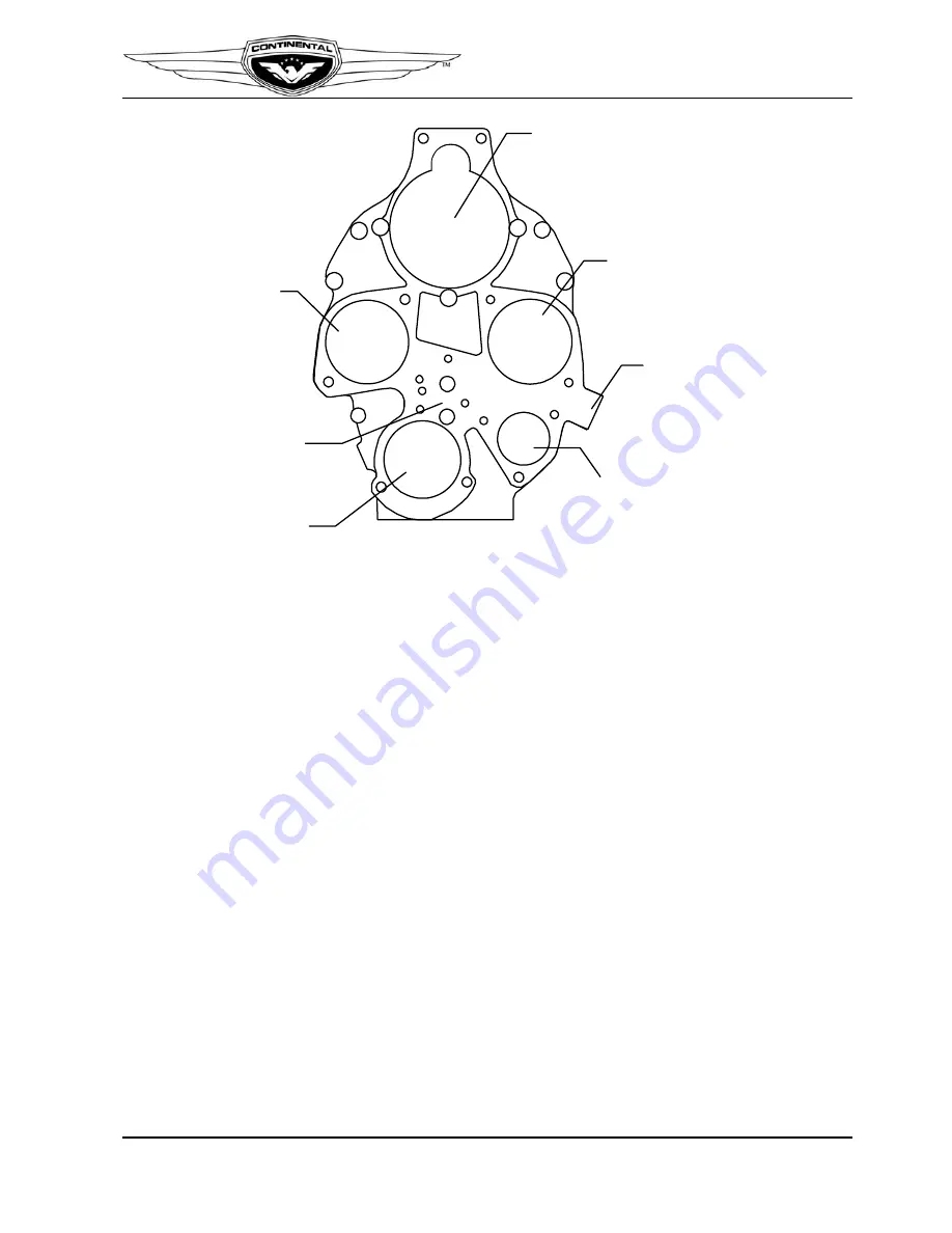
Figure 2-8. Accessory Case Features
2-2.4. Cylinders
The IO-240 engine have four, horizontally-opposed, air cooled cylinders, two on the left
side and two on the right side of the engine. The cylinders, pistons and valve drive train
provide the momentum to sustain crankshaft movement. Aviation fuel and air are drawn
into a cylinder during the intake stroke, compressed by the piston during the compression
stroke and then ignited by a high intensity spark from each spark plug (two per cylinder).
As the mixture is ignited, the expanding gases force the piston to move inward toward the
crankshaft during the power stroke.
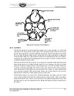
The head and barrel assembly (Figure 2-9) consists of externally finned aluminum alloy
head casting and a steel, nitrided cylinder barrel for wear resistance. Helical coil thread
inserts are installed in upper and lower spark plugs holes. A rotocoil assembly retains two
concentric springs surrounding the exhaust valve and is locked to the stem by tapered,
semi-circular keys which engage grooves around the valve stems. An outer retainer holds
two concentric springs which surround the intake valve and is locked to the stem by
tapered, semi-circular keys which engage grooves on the stem.
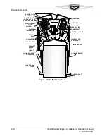
IO-240 Series engines use a cross flow cylinder head design. The intake ports are located
on top of the cylinder head while the exhaust ports are located below. There are separate
intake and exhaust valve rocker covers made from zinc-plated stamped sheet steel. This
cylinder design is used in conjunction with a Balanced Induction System mounted above
the engine.
STARTER MOUNTING
PAD
MAGNETO MOUNTING
PAD
TACH DRIVE
MOUNTING
PAD
ALTERNATOR
MOUNTING
PAD
OIL SCREEN
HOUSING
MOUNTING
PAD
OIL PRESSURE
RELIEF VALVE
HOUSING
MAGNETO
MOUNTING
PAD
Summary of Contents for IO-240-A
Page 145: ......
Page 146: ...www continentalmotors aero ...


