Teledyne Continental Motors, Inc.
TM
Troubleshooting
8-14.
IOF-240-B FADEC Schematics
The IOF-240-B FADEC schematic diagrams are included for FADEC troubleshooting.
Refer to the airframe schematics for the cabin harness schematics.
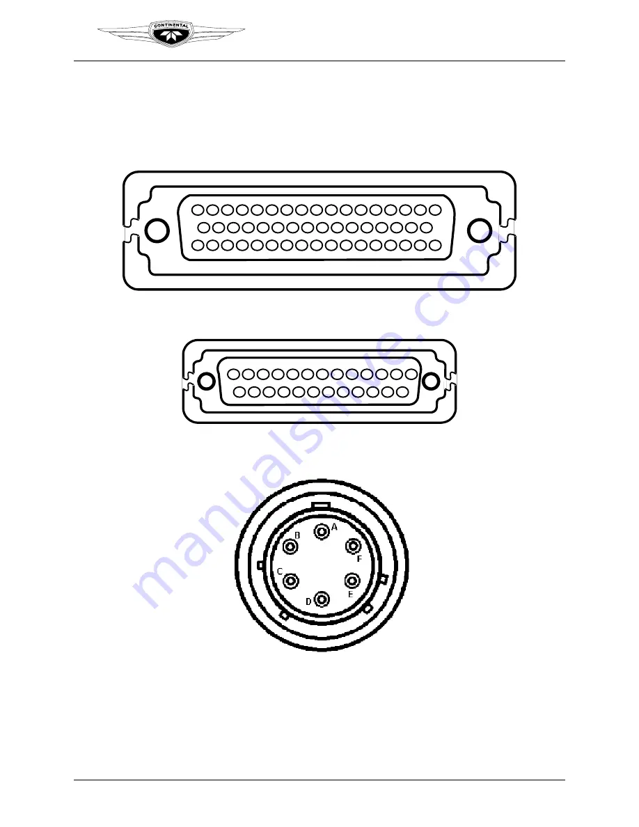
8-14.1. Connector Layout
34 35 36 37 38 39 40 41 42 43 44 45 46 47 48 49 50
1
2
3
4
5
6
7
8
9
10 11 12 13 14 15 16 17
18 19 20 21 22 23 24 25 26 27 28 29 30 31 32 33
Figure 8-4.
P1 and P2 50-pin connectors
1
2
3
4
5
6
7
8
9
10 11 12 13
14 15 16 17 18 19 20 21 22 23 24 25
Figure 8-5.
P 3 and 4 25-pin connectors
Figure 8-6.
P9, 10, 11, and 12 6-pin connectors
IOF-240 Series Engine Maintenance Manual
8-35
31 August 2007
Change 1


