Non-Overhaul Removal and Replacement
Teledyne Continental Motors, Inc.
TM
10-8
IOF-240 Series Engine Maintenance Manual
29 November 2006
10-2.2. Fuel Pump Installation
Procedure
WARNING
If engine electrical power is not disconnected, a faulty ignition
circuit could allow the engine to start and the propeller to
rotate. Do not stand or place equipment within the arc of the
propeller.
1.
Disconnect engine electrical power; turn the Ignition Switch to the OFF position.
2.
Apply F/I sealant to the fuel pump fitting threads; Install the fuel pump fittings,
oriented in the same manner as on the removed pump; torque the fittings according to
Appendix B.
3.
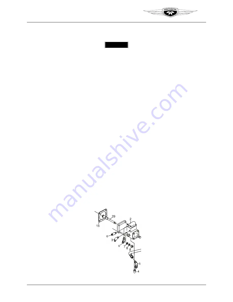
Apply Molyshield Grease to the fuel pump drive coupling (29).
4.
Install the fuel pump drive coupling (29) in the fuel pump.
5.
Apply a thin translucent coat of Gasket Maker to the mating surface of the crankcase
and new gasket (15). Install a new gasket (15) on the fuel pump (15).
6.
Lubricate the fuel pump cavity with clean 50 weight aviation engine oil.
7.
Install the fuel pump (2) on the crankcase with washers (7), new lock washers (8),
and nuts (9). Torque the fastening nuts (9) per Appendix B.
8.
Connect the aircraft fuel supply to the fuel pump inlet fitting (3). Connect the fuel
pump outlet hose (5) to the pump outlet fitting (4).
9.
Connect the vapor return hose to the vapor return fitting (6). Connect the aircraft fuel
drain line to the fuel pump drain fitting (6) on the bottom of the pump.
10.
Torque all fittings and hoses according to Appendix B.
11.
Perform a fuel system leak check with the aircraft boost pump ON.
12.
Perform an “Engine Operational Check” (Chapter 6, Operational Performance
Checks).
Figure 10-2.
Fuel Pump with fittings


