Non-Overhaul Removal and Replacement
Teledyne Continental Motors, Inc.
TM
10-24
IOF-550 Permold Series Engine Maintenance Manual
1 April 2007
5.
Cut the leads to be replaced two inches longer than the replacement leads which will
result in an acceptable 4-inch overlap.
6.
Mark the braided outer shield of the lead wire 1-5/8” from the cut end.
7.
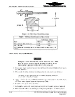
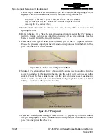
Carefully split the jacket lengthwise, with a utility knife, beginning at the 1-5/8-inch
mark and continuing to the cut end as shown in Figure 10-10. Use care to avoid
cutting or nicking the insulation beneath the jacket. The split lead wire jacket should
appear as shown in the photo in Figure 10-11.
CAUTION: When stripping the shield, avoid nicking or cutting the
insulation of the two conductors within the lead.
Figure 10-10.
Stripping the Overbraid Jacket
Figure 10-11.
Shield Stripping of EGT Sensor Wire
8.
Fold the split portion of the shield back.
9.
Use small shears to trim the braid to the mark at 1-5/8” from the end of the wire.
10.
Strip the shield to expose the inner insulation. Using a sharp utility knife, carefully
split the inner insulation longitudinally beginning at the 1-5/8-inch mark and
continuing to the cut end (Figure 10-12).
Figure 10-12.
Inner Jacket Split


